


6-3
Maintenance and Troubleshooting
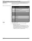
Flow in Pipe,
Incorrect Output
(continued)
50/60 Hz Measurement
• May indicate electrical or magnetic interference; check the meter ground.
• If the meter is located near a large motor or electric furnace, try different meter orientations to reduce the
noise. Magnetic fields must be less than 5 gauss.
• In remote-mount installations, try integral mount to see if the problem is corrected. Measure ac voltage from
the electronics housing to the SMA connector. The voltage must be <1Vrms.
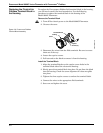
Sensor
• The sensor should resist removal because the interference fit has extremely tight tolerances. Repeated
removal and installation of the sensor will loosen it. If the sensor is loose, replace the sensor.
• Inspect and tighten the sensor connector if necessary.
• Inspect the coaxial sensor cable for cracks. Replace it if necessary.
• Check torque on the sensor nut (32 ft-lb).
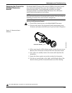
• Check that sensor impedance >10 Megaohms. Replace the sensor if necessary (see “Replacing the Sensor”
on page 6-12).
• Measure sensor capacitance at the SMA connector (100–200pF).
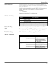
Output with No
Actual Flow
Basics
• Check and correct configuration parameters in this order: K-factor, service type, materials, units, process
temperature, damping value, density, pipe diameter, LRV, URV, trigger level, low-flow cutoff.
• Check sizing; make sure flow is within measurable flow limits.
• Refer to live.
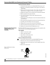
Vibration Problem
• Adjust signal processing parameters:
• Adjust low-flow cutoff to higher flow rates (if the application allows). Move the low-flow cutoff up one notch
and measure the process variable. Continue moving the low-flow cutoff until the problem is corrected or the
flow range is too limited for the application.
• Adjust the trigger level up; the default trigger level is four. Adjust it one notch and measure the process variable.
Continue moving the trigger level until the output reaches zero or the trigger level reaches a value of seven. Be
sure to check the process variable with the process flowing once you are done adjusting the trigger level.
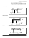
• Rotate the meter 90°.
• Add support to the line near the meter to damp the vibration.
50/60 Hz Measurement
• May indicate electrical or magnetic interference; check the meter ground.
• If the meter is located near a large motor or electric furnace, try different meter orientations to reduce the
noise. Magnetic fields must be less than 5 gauss.
• In remote mount installations, try integral mount to see if the problem is corrected. Measure ac voltage from the
electronics housing to the SMA connector. The voltage must be <1Vrms.
Application Problems
• Check if the pump pulsations are disturbing flow. Adjust the signal processing parameters.
• Add flow straightener.
• Check all valves and make sure they are closed.
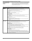
Symptom Corrective Action