


2-19
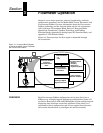
Installation
ELECTRICAL
CONSIDERATIONS
Proper electrical installation is necessary to prevent errors due to
electrical noise and interference. Shielded cable should be used for best
results in electrically noisy environments.
Power Supply The transmitter requires a minimum of 9 V dc and a maximum of 32 V
dc at the transmitter power terminals.
NOTES
• Do not exceed 32 V dc at the transmitter terminals.
• Do not apply ac line voltage to the transmitter terminals.
Improper supply voltage can damage the transmitter.
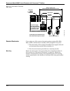
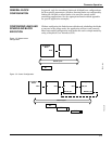
Power Conditioning Each fieldbus power supply requires a power conditioner to decouple
the power supply output from the fieldbus wiring segment.
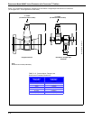
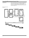
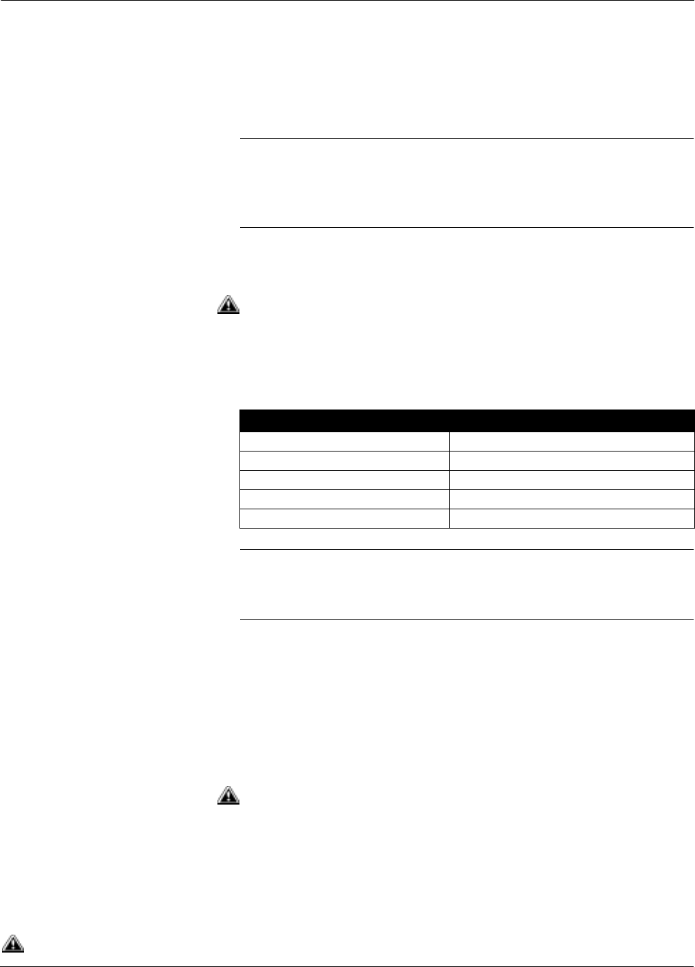
Field Wiring All power to the transmitter is supplied over the segment wiring. Use
shielded, twisted pair for best results. For new installations or to get
maximum performance, twisted pair cable designed especially for
fieldbus should be used. Table 2-16 details cable characteristics and
ideal specifications.
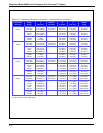
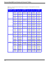
TABLE 2-16.
Ideal Cable Specifications
for Fieldbus Wiring.
NOTE
The number of devices on a fieldbus segment is limited by the power
supply voltage, the resistance of the cable, and the amount of current
drawn by each device.
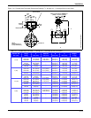
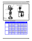
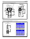
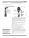
Transmitter Wiring Connection To make the transmitter wiring connection, remove the FIELD
TERMINALS end cover on the electronics housing. Connect the power
leads to the positive (+) and negative (–) terminals. The power
terminals are polarity insensitive: the polarity of the dc power leads
does not matter when connecting to the power terminals.
When wiring to screw terminals, crimped lugs are recommended.
Tighten the terminals to ensure adequate contact. No additional power
wiring is required.
Both transmitter covers must be fully engaged to meet explosion proof
requirements. Do not remove the transmitter covers in an explosive
atmosphere when the transmitter is powered.
See “Safety Messages” on page 2-1 for complete warning information.
Characteristic Ideal Specification
Impedance 100 Ohms ± 20 % at 31.25 kHz
Wire Size 18 AWG (0,8 mm
2
)
Shield Coverage 90 %
Attenuation 3 db/km
Capacitive Unbalance 2 nF/km