


Rosemount Model 8800C Vortex Flowmeter with FOUNDATION
™
Fieldbus
4-4
Parameters and
Descriptions
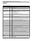
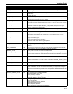
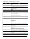
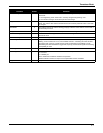
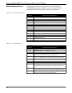
TABLE 4-1. Transducer Block Parameters.
Parameter
Index
Number
Definition
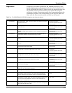
ALERT_KEY 4 The alert key is the identification number of the plant unit. This information may be used in the
host for sorting alarms, etc.
BASE_COMPRESSIBILITY 57 Base compressibility is the compressibility of the process fluid at the base temperature and
base pressure. It is used to calculate the PROCESS_DENSITY_RATIO and is not limit
checked.
BASE_PRESSURE 55 Base pressure is the pressure from which the PROCESS_DENSITY_RATIO is calculated.
BASE_PRESSURE_UNITS 56 The engineering units of base pressure:
1137 = bar (absolute)
1142 = pounds per square inch (absolute)
1545 = Megapascals (absolute)
1547 = Kilopascals (absolute)
1557 = Kilograms per square centimeter (absolute)
BASE_TEMP_UNITS 54 The engineering units of base temperature:
1001 = °C
1002 = °F
BASE_TEMPERATURE 53 The configured base temperature is the temperature from which the
PROCESS_DENSITY_RATIO is calculated.
BLOCK_ALM 8 The block alarm is used for all configuration, hardware, connection failure, or system
problems in the block. The cause of the alert is entered in the subcode field. The first alert to
become active will set the Active status in the status parameter. As soon as the unreported
status is cleared by the alert reporting task, another block alert may be reported without
clearing the Active status, if the subcode has changed.
BLOCK_ERR 6 This parameter reflects the error status of the hardware or software components associated
with a block. The parameter is a bit string, so multiple errors may be shown.
CAL_MIN_SPAN 18 CAL_MIN_SPAN is the minimum span that must be used between the calibration high and
low points.
CAL_POINT_HI 16 CAL_POINT_HI is the value of the primary value measurement used for the high calibration
point.
CAL_POINT_LO 17 CAL_POINT_LO is the value of the primary value measurement used for the low calibration
point.
CAL_UNIT 19 CAL_UNIT specifies the units used for the calibration inputs.
COLLECTION_DIRECTORY 12 The collection directory specifies the number, starting indices, and DD item IDs of the data
collections in each transducer within a transducer block.
COMPD_K_FACTOR 33 This parameter represents the K-factor after it has been compensated for process
temperature, materials, installation effects, etc. Units are reflected in K_FACTOR_UNITS.
DAMPING 30 Damping is the sampling interval used to smooth output using a first-order linear filter. Limits
are 0.2 to 255 seconds.
ELECTRONICS_STATUS 69 This parameter represents the transducer block electronics status. See “Diagnostics” on
page 4-9.
FILTER_AUTO_ADJUST 42 Selecting a fluid density close to the process density will adjust the Trigger Level, Low Flow
Cutoff, and Low Pass Filter to values that will work well for most applications.
FLANGE_TYPE 36 Flange type specifies the wafer or the flange construction material (i.e. ANSI 150, ANSI 300,
ANSI 600, PN64, JIS 10K, etc.). Flange type is used as an input to the compensated K-factor
calculation.
INSTALLATION_EFFECTS 32 An adjustment to the Compensated K-Factor to account for less than ideal upstream
piping effects.
K_FACTOR 31 The K-factor is the meter body calibration number. Units are reflected in K_FACTOR_UNITS.
K_FACTOR_UNITS 34 K-factor units are the engineering units to be applied to the K_FACTOR and
COMPD_K_FACTOR.
0 = Pulses per gallon