


Rosemount Model 8800C Vortex Flowmeter with FOUNDATION
™
Fieldbus
6-6
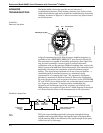
Shedding Frequency Out Shedding frequency out is probably the easiest point to measure and
interpret; it is the final waveform after all filtering has taken place.
Shedding frequency out is the flow signal that is sent to the
microprocessor to be processed into outputs. Check this point first, as it
will allow you to see the final waveform (after filtering) before it goes to
the microprocessor.
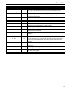
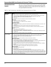
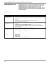
TABLE 6-2. Troubleshooting—
Shedding Frequency Out.
Symptom Corrective Action
Clean Signals at TP1 and
Shedding Frequency Out,
But Incorrect Output
Basics
• Check and correct configuration parameters in this order: K-factor, service type, materials, units, process
temperature, damping value, density, density ratio, pipe diameter, LRV, URV, LP corner, trigger level, and
low-flow cutoff.
• Refer to live.
• See Section 9: Electronics Verification for electronics verification procedure.
• Refer to Table 6-1 for further troubleshooting.
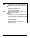
No Pulse at
Shedding Frequency Out
Basics
• Check TP1.
• Check electronics via flow Flow Simulation mode (see Section 9: Electronics Verification).
• Check electronics with an external frequency generator.
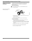
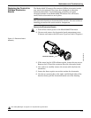
• Check that sensor impedance >10 Megaohms. Replace sensor if necessary. (See “Replacing the
Sensor” on page 6-12.)
• Measure sensor capacitance at SMA connector (100–200pF).
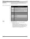
Noisy Signal at
Shedding Frequency Out
Basics
• Simulate signal with frequency generators or Flow Simulation mode
(see Section 9: Electronics Verification).
• Optimize filter (gas); increase filtering of low pass filter.
• Consult the factory.
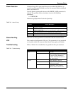
Missing Pulse at
Shedding Frequency Out
Basics
• Low back pressure
• Viscosity too high
• Density too low
• Check the sensor.
• Too much filtering; check the signal/trigger level rate.