


3-3
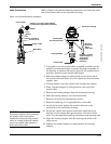
Flowmeter Operation
GENERAL BLOCK
CONFIGURATION
In general, only the transducer block and AI block have configurations
for flow-specific parameters. All other function blocks are configured by
linking the AI block to other blocks to be used for control and/or
monitoring applications. See the appropriate function block appendix
for specific application examples.
CONFIGURING LINKS AND
SCHEDULING BLOCK
EXECUTION
Without configuring the links between blocks and scheduling the blocks
to execute in the proper order, the application will not work correctly.
Most hosts and/or configuration tools make this task a simple matter by
using a Graphical User Interface (GUI).
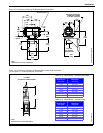
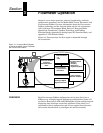
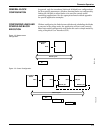
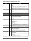
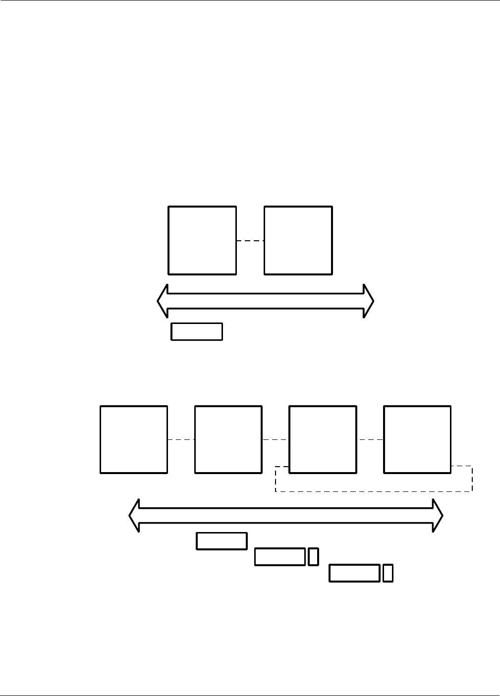
Figure 3-2. Measurement
Configuration.
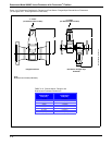
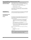
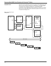
Figure 3-3. Control Configuration.
Transducer
Block
AI Block
Flow
AI
Macro Cycle
IN
FBUS_48A
IN
BKCAL_IN
PID Block
BKCAL_OU
Analog Output
CAS_IN
PID
AO
Transducer
Block
Flow
AI Block
OUT
IN
AI1
Macro Cycle
OUT
FBUS_47A