


7-3
Options
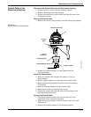
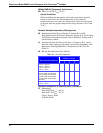
Installing the Indicator For flowmeters ordered with the LCD indicator, the indicator is shipped
installed. When purchased separately from the Model 8800C
Flowmeter, you must install the indicator using a small instrument
screwdriver and the indicator kit. The indicator kit includes:
• One LCD indicator assembly
• One extended cover with O-ring installed
• One connector
• Two mounting screws
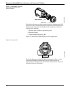
Referring to Figure 7-1, use the following steps to install the LCD
indicator:
1. If the flowmeter is installed in a loop, secure the loop and
disconnect the power.
2. Remove the flowmeter cover on the electronics side.
NOTE
The circuit board is electrostatically sensitive. Be sure to observe
handling precautions for static-sensitive components.
3. Insert the mounting screws into the LCD indicator.
4. Remove the two jumpers on the circuit board that coincide with
the SIMULATE ENABLE and the SECURITY settings.
5. Insert the connector into the SIMULATE ENABLE/ SECURITY
junction.
6. Gently slide the LCD indicator onto the connector and tighten
the screws into place.
7. Insert jumpers into SIMULATE ENABLE and SECURITY
positions on the face of the LCD indicator.
8. Attach the extended cover and tighten at least one-third turn
past O-ring contact.
NOTE
The indicator may be installed in 90° increments for easy viewing. One
of the four connectors on the back of the indicator assembly must be
positioned to fit into the ten-pin connector on the electronic board stack.
Note the following LCD temperature limits:
Operating: –4 to 185 °F (–20 to 85 °C).
Storage: –50 to 185 °F (–46 to 85 °C).