


Rosemount Model 8800C Vortex Flowmeter with FOUNDATION
™
Fieldbus
I-2
Device descriptions
definition ....................A-2
Device ID ...................... 2-22
Device tag ...................... 3-2
Diagram
PID block ................C-1,C-5
Direct action ....................C-8
Direct signal conversion ..........B-5
Disassembly Procedure .......... 6-7
Display ........................ 4-15
Download .......................A-6
DV_HI_LIM
PID block ....................C-9
DV_HI_PRI
PID block ....................C-9
DV_LO_LIM
PID block ....................C-9
DV_LO_PRI
PID block ....................C-9
E
Electrical Installation
Wiring ...................... 2-19
Electronics Boards Replacement .. 6-9
Electronics Considerations ....... 2-9
Electronics Housing Replacement 6-10
ELECTRONICS_STATUS
transducer block ..............4-9
Environmental Considerations ... 2-3
Execution time .................. 8-8
F
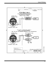
Factory Mutual
intrinsic safety installation drawings .
E-1
Failure Mode Switch ............. 2-4
Feedforward control ............C-12
FF_GAIN
PID block ....................C-6
FF_SCALE
PID block ....................C-6
FF_VAL
PID block ................C-1,C-6
Fieldbus
addresses ....................A-5
network
definition
.................A-3
segment .....................A-3
Filter Auto Adjust .............. 4-15
Filter Trigger Level ............. 4-14
FILTER_TYPE
PID block ....................C-6
Filtering .......................4-14
AI block ......................B-4
PID block .....................C-6
Flange Bolt Torquing Sequence ...2-9
Flange Bolts .....................2-5
Flange Type ....................4-14
Flanged-style Flowmeter
Installation ....................2-8
Flanged-style Flowmeter Mounting 2-9
Flow Direction ...................2-5
Flow Rate Value ................4-14
Flow Simulation ................4-15
Flow Units ................4-10,4-11
Flowmeter Grounding ............2-9
Flowmeter Orientation ...........2-2
Foundation Fieldbus specifications 8-8
Foundation Fieldbus Terminal Block Assembly
6-8
Function Block Schedule .........A-7
Function blocks
configuring links and scheduling
block execution
...............3-3
definition .....................A-1
G
Gaskets .........................2-5
General Considerations ..........2-1
H
Handling ........................2-5
Hardware Configuration ..........2-4
Hardware Maintenance ..........6-7
Hardware Replacement
Electronics Boards .............6-9
Electronics Housing ...........6-10
Remote Electronics ............6-19
Sensor ......................6-12
Terminal Block ................6-8
HI_HI_LIM
PID block .....................C-9
HI_HI_PRI
PID block .....................C-9
HI_LIM
PID block .....................C-9
HI_PRI
PID block .....................C-9
High-Point Installation ..........2-10
I
IN
PID block .....................C-1
Indirect signal conversion ........B-5