


9-3
Electronics Verification
Electronics Verification
UsinganExternal
Frequency Generator
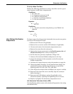
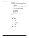
If an external frequency source is desirable, then test points at the top
of the electronics are available (see Figure 9-2).
Tools Needed
•F
OUNDATION fieldbus-compliant host, such as DeltaV
with AMSinside
• Standard sinewave generator
1. Remove the electronics compartment cover.
2. Remove the two screws and the LCD indicator if applicable.
3. Connect a F
OUNDATION fieldbus-compliant host, such as DeltaV
with AMSinside to the loop.
4. Access the flow simulation menu on the communicator and select
“Sim-External Generator.” This will effectively disconnect the
Model 8800C sensor input from the charge amplifier input of the
electronics (see Figure 6-2 on page 6-4). The simulated flow
and/or the shedding frequency values will now be accessible via a
F
OUNDATION fieldbus-compliant host, such as DeltaV with
AMSinside.
5. Connect the sinewave generator to the “TEST FREQ IN” and
“GND” points as shown in Figure 9-2.
6. Set the sinewave generator amplitude to 2Vpp±10%.
7. Select the desired sinewave generator frequency.
8. Verify the generator frequency against the frequency displayed
on a F
OUNDATION fieldbus-compliant host, such as DeltaV with
AMSinside.
9. Select “Sim Disabled” to exit the Flow Simulation Mode.
10. Reconnect the LCD indicator option (if applicable) to the
electronics board by replacing and tightening the two screws.
11. Replace and tighten the electronics compartment cover.
NOTE
To manually disconnect the sensor for precautionary measures, see
page 6-12 for details.
Figure 9-2. Test Frequency Output and
Chassis Ground Points.
8800-0000P03B