


2 - NAV PAGES
44
190-00356-00 Rev E
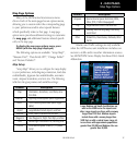
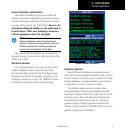
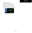
To enable TERRAIN:
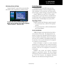
Enabling Terrain
1. Select the TERRAIN Page and press MENU.
“Enable Terrain?” is selected by default.
2. Press ENT. The TERRAIN system is functional
again.
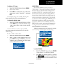
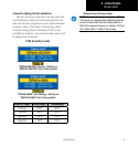
Terrain Symbols
The symbols shown below are used to represent
obstacles and potential impact points on the Terrain
Page. Note that obstacle symbols are shown on display
zoom ranges up to 10
NM
:
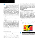
The Garmin TERRAIN system uses yellow (caution)
and red (warning) to depict terrain information relative
to aircraft altitude.
Each color is associated with an
alert severity level. Terrain graphics and visual annun-
ciations also use these color assignments.
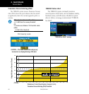
NOTE: If an obstacle and the projected flight path of
the aircraft intersect, the display automatically zooms in
to the closest potential point of impact on the TERRAIN
page.
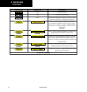
Terrain Operation
Obstacle Symbol
Unlighted Obstacle Lighted Obstacle Color
(Alert Level)
TERRAIN/Obstacle
Location
< 1000’ AGL > 1000’ AGL < 1000’ AGL > 1000’ AGL
Red
(Warning)
Terrain/Obstacle above or
within 100 ft below current
aircraft altitude
Yellow
(Caution)
Terrain/Obstacle between
100 ft and 1000 ft below the
aircraft altitude
Terrain Color Symbology
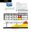
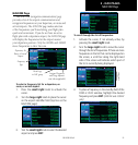
Potential Impact Point
Unlighted Obstacle
Projected Flight Path
£äääÊvÌÊ
£ääÊvÌÊ/ÀiÃ`Ê
4ERRAINMORETHANFTBELOWTHEAIRCRAFTALTITUDE"LACK
4ERRAINBETWEENFTANDFTBELOWTHE
AIRCRAFTALTITUDE9ELLOW
4ERRAINABOVEOR
WITHINFT
BELOWTHEAIRCRAFT
ALTITUDE2ED
TERRAIN Altitude/Color Correlation