3 - 32
INSP
ADJ
STEERING SYSTEM INSPECTION/
TOE-IN ADJUSTMENT
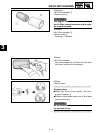
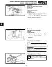
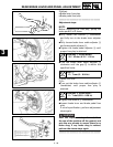
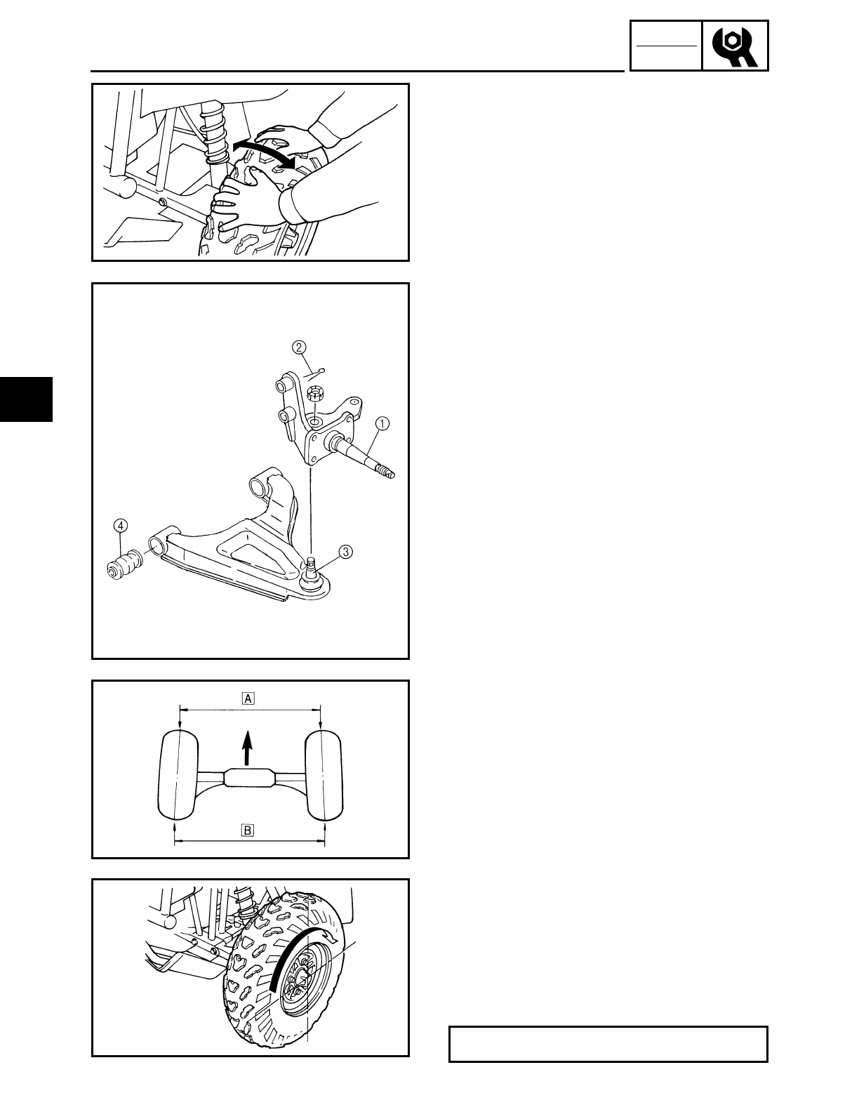
4.Raise the front end of the machine so that
there is no weight on the front wheels.
5.Check:
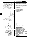
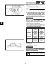
● Knuckles and/or wheel bearings
Move the wheels laterally back and forth.
Excessive free play → Replace the follow-
ing parts.
1) Wheel bearings
2) Knuckle shaft(s) 1
3) Cotter pin(s) 2
4) Stud boll(s) 3 (lower arm)
5) Bushings 4 (lower arm)
Refer to the “STEERING SYSTEM” section
in CHAPTER 7.
TOE-IN ADJUSTMENT
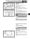
1.Place the machine on a level place.
2.Measure:
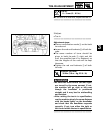
● Toe-in
Out of specification → Adjust.
**********************************
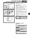
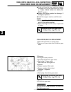
Toe-in measurement steps:
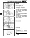
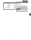
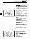
●Mark both front tire tread centers.
●Raise the front end of the machine so that
there is no weight on the front tires.
●Fix the handlebar straight ahead.
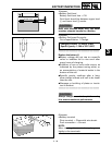
●Measure the width Å Between the marks.
●Rotate the front tires 180 degrees until the
mark come exactly opposite.
●Measure the width ı between the marks.
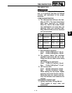
●Calculate the toe-in using the formula
given below.
Toe-in = ı – Å:
3


