


41–01 Driveline Inspecting
Inspecting
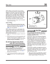
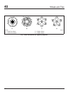
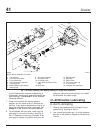
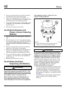
1. Check that the yoke-strap capscrews (see Fig. 1,
Ref. 4) are tightened as follows:
• Dana Spicer 1590 and 1610: 50 to 60 lbf·ft
(68 to 81 N·m)
• Dana Spicer 1710: 125 to 135 lbf·ft (170 to
183 N·m)
CAUTION
Do not overtighten the yoke-strap capscrews, due
to the extreme load occurring at high-speed rota-
tion. A loose or broken capscrew at any point in
the driveline weakens the driveline connection,
which could eventually result in serious vehicle
damage.
2. Check each of the output and input end yokes
(see Fig. 1, Refs. 2 and 11) for cracks and
looseness. Replace cracked yokes. If any end
yoke can be moved in or out on its shaft, or can
be rocked on its shaft, disconnect the driveshaft
and U-joint from the end yoke. Check the drive
component’s shaft seal for leakage or other vis-
ible damage that may have been caused by the
loose yoke. Replace the seal if needed. Tighten
the end-yoke nut to the value in Table 1.Ifthe
end yoke is still loose after tightening the yoke
nut, install a new yoke and yoke nut.
NOTE: If the end-yoke locknut was removed for
any reason, install a new one.
3. Check the U-joint assemblies for wear by at-
tempting to move the driveshaft up and down,
and from side to side. If movement of the U-joint
trunnion in the bearings is greater than 0.006
inch (0.15 mm), replace the U-joint assembly.
4. Check the midship bearing and bracket for loose-
ness and deterioration by attempting to move the
driveshaft up and down, and from side to side. If
the bearing is loose on its shaft, or rattles, re-
place it. If the bearing bracket is loose on the
frame, or the bearing mount is loose on the
bracket, tighten the mounting bolt nuts 91 lbf·ft
(123 N·m). Replace the midship bearing assem-
bly if the rubber cushion is worn or oil-soaked.
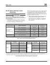
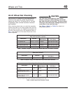
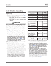
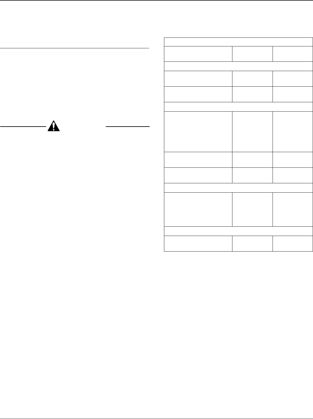
End-Yoke Nut Torque Specifications
Description Thread Size
Torque:
lbf·ft (N·m)
Transmissions
Allison AT-545 1/2–20
*
100–120
(140–160)
Allison MD Series 2–16
600–800
(815–1085)
Single Axle Input Shaft
Meritor RS–13–120,
RS–15–120 and –210,
RS–17–140 and –20,
RS–19–145 and –220,
and
RS–21–145 and –230
M32 x 1.5
740–920
(1000–1250)
Meritor RS–23–160 M45 x 1.5
1000–1230
(1355–1670)
Meritor RS–23–240 M39 x 1.5
920–1130
(1250–1530)
Tandem Axle Input and Output Shafts
Meritor
RD– and RR–17–145,
(of RT–34–145), and
RD– and RR–20–145
(of RT–40–145)
M39 x 1.5
920–1130
(1250–1530)
Coupling Shaft (Midship Bearings)
Dana Spicer 1590, 1610,
and 1710
1-1/4–18
475–525
(644–712)
*
The Allison AT-545 transmission output shaft end-yoke is retained by a
1/2-20 x 1-1/2-inch bolt and a 1-1/16-inch washer. Both the bolt and the
washer must be replaced each time they are removed.
Table 1, End-Yoke Nut Torque Specifications
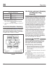
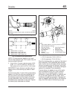
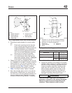
5. Check the slip-joints for spline wear by trying to
bend the sleeve-yoke and splined shaft back and
forth (see Fig. 2). If looseness is greater than
0.007 inch (0.18 mm), replace both the sleeve-
yoke and the splined shaft.
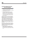
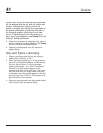
6. Check the driveshaft tubes for dents, bends,
twists, or other damage. If any tube appears to
be damaged, remove the driveshaft and check
the runout on the tube. If the tube is not straight
(and cannot be straightened) within 0.015 inch
(0.38 mm) on the slip-joint seal surface of the
splined shaft, 0.020 inch (0.51 mm) on the tube
3 inches (76 mm) from the front and rear welds,
and 0.025 inch (0.635 mm) at the center of the
tube, replace the tube. See Fig. 3.
Driveline 41
Acterra Maintenance Manual, March 2000 41/1