


3. Clean any road grime from the relay valve and
any debris from the valve exhaust port.
4. Listen for air leakage around the fittings or ex-
haust port. Tighten the fittings as necessary. Use
two wrenches to avoid twisting the tubing.
5. If the valve fails this check or is damaged, repair
or replace it. For instructions, see the Midland
service manual.
6. Remove the chocks from the tires.
42–06 Quick Release and
Flipper Valves Checking,
Midland
1. Park the vehicle on a level surface. Chock the
tires.
2. Start the engine and run it long enough to pres-
surize the air system to at least 80 psi (550 kPa).
Turn off the engine. Repeat as necessary to
maintain 80 psi (550 kPa) pressure during these
checks.
3. Clean any road grime from the valves and any
material from the valves’ exhaust ports.
4. Listen for air leakage around the fittings and ex-
haust ports. Tighten the fittings as necessary.
Use two wrenches to avoid twisting the tubing.
5. If any valve fails this check or is damaged, repair
or replace it. For instructions, see the Midland
service manual.
6. Remove the chocks from the tires.
42–07 Brake Chamber
Inspecting (All Models)
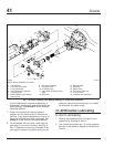
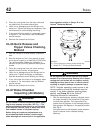
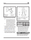
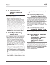
WARNING
Do not loosen or remove the parking brake clamp
ring for any purpose at any time. See Fig. 1. The
parking/emergency brake section is not intended
to be serviced. Serious injury or death may result
from sudden release of the power spring.
Before doing any repairs or adjustments on a
service/parking brake chamber, read the appli-
cable warnings and instructions in the applicable
brake chamber section in Group 42 of the
Acterra
®
Workshop Manual
.
WARNING
Do not operate the vehicle with the front brakes
backed off or disconnected. Backing off or discon-
necting the front brakes will not improve vehicle
handling and may lead to loss of vehicle control
resulting in property damage or personal injury.
NOTE: Vehicles operating under severe or ad-
verse conditions should be checked more fre-
quently. If the brake chamber requires disas-
sembly, see Group 42 of the
Acterra
®
Workshop Manual
for instructions.
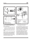
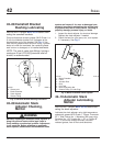
1. With the slack adjuster properly adjusted, check
the angle formed by the centerline of the piston
rod and slack adjuster. This angle should be
greater than 90 degrees in the released position
and approach 90 degrees in the applied position.
See Fig. 2.
At angles less than 90 degrees, brake chamber
force is reduced, which reduces braking
efficiency.
1
A
02/22/2000
f421352
A. Do not remove the factory-sealed clamp ring.
1. Model TR-T (TR Series) Brake Chamber
Fig. 1, MGM Brake Chamber
Brakes42
Acterra Maintenance Manual, October 200742/2