


down, in, and out. If there is any movement, re-
place the torque arm.
2. Inspect the rubber bushing ends. Replace the
torque arm if there are gaps between the rubber
bushing and the pin or the outer steel sleeve, if
either bushing end contacts a torque arm pin
mounting bolt, if there are cracks in the bushing,
or if part of the rubber bushing extends beyond
the outside diameter of the outer bushing sleeve.
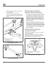
Chalmers Suspension Checking
Chock the front wheels to prevent the vehicle from
moving. Place the transmission in neutral, and re-
lease the spring or driveline brakes before inspecting
the rear suspension.
Power wash the Chalmers rear suspension, or clean
it with a hard-bristle brush before performing a visual
inspection.
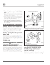
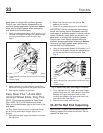
1. Inspect the rubber bushings for cracks or other
damage.
Try to move the torque rod ends using your
hands only, and check for any free-play. If free-
play is felt, replace the torque rod end bushing.
Do not use a pry bar to check for free-play. Use
of a pry bar may lead to premature bushing re-
placement. See Group 32 of the
Acterra
®
Work-
shop Manual
for replacement instructions.
2. If equipped with optional shock absorbers, check
for worn, broken, or damaged shock bushings,
heavy corrosion on the shock absorber body, or
fluid leaking from the shock absorber. Replace
the shock absorbers if any of these conditions
are found; see Group 32 of the
Acterra
®
Work-
shop Manual
.
3. Lift the rear of the vehicle and support the frame
on jack stands to unload the suspension compo-
nents. The vehicle is lifted high enough when the
beam ends are off of the saddles. All jack stands
must be of sufficient strength and rigidity to
safely support the vehicle. Do not perform any
work on or around a vehicle that is supported
solely by a lifting device.
Visually inspect the walking beam for cracks, or
other damage. If damage is found, see Group
32 of the
Acterra
®
Workshop Manual
for replace-
ment instructions.
Keep the vehicle supported by the jack stands
for the next operation.
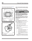
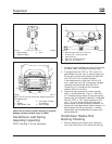
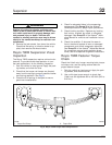
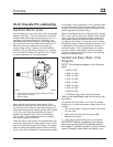
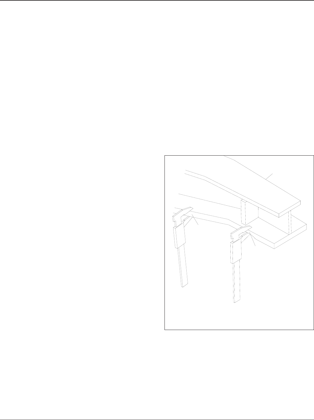
4. Manipulate the walking beam so that a microme-
ter, vernier, or dial caliper can be used to deter-
mine the wear area thickness on the bottom
face. See Fig. 8. Measurements should be taken
a minimum of 1/2 inch (13 mm) from the beam
flange edges to eliminate any edge wear that
may have occurred. Subtract the wear area
thickness (see Fig. 8, Ref. B), from the non-wear
area (see Fig. 8, Ref. A), to determine the
amount of wear.
If the beams show any wear greater than the
allowable 0.062-inch (1.5-mm) wear, a Chalmers
wear plate must be installed, or the walking
beam must be replaced. See Group 32 of the
Acterra
®
Workshop Manual
for repair and re-
placement instructions.
5. Rotate the restrictor cans 360 degrees and in-
spect the cans for cracks, severe corrosion, and
distortion. If any of these conditions are present,
or the restrictor can is missing, replace the re-
strictor can. See Group 32 of the
Acterra
®
Work-
shop Manual
for replacement instructions.
09/27/95
f320432
1
A
B
A. Non-Wear Area
B. Wear Area
1. Walking Beam
Fig. 8, Walking Beam End Wear Thickness
Suspension32
Acterra Maintenance Manual, September 200232/6