


2. Check each brake chamber for correct installa-
tion.
2.1 Check each mounting stud for the pres-
ence of prevailing torque locknuts and
hardened flatwashers. Make sure that the
hardened flatwashers are installed be-
tween the mounting bracket and the lock-
nuts. Do not install flatwashers touching
the service (non-pressure) chamber.
2.2 If the locknuts are loose, tighten them.
For correct torque values, see the appli-
cable brake chamber section in Group 42
of the
Acterra
®
Workshop Manual
.
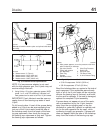
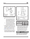
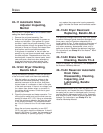
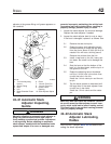
3. Observe the piston rod engagement with the cle-
vis. Engagement of at least 7 threads is required;
there should be 1-inch (25-mm) clearance from
the centerline of the clevis pin hole to the end of
the piston rod. See Fig. 3. Adjust if needed.
4. Check the tightness of the piston rod nut. See
Table 1 for torque values. Tighten if needed.
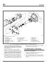
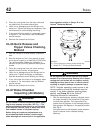
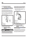
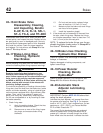
5. See if the chamber piston rod is in line with the
slack adjuster. Misalignment can cause the pis-
ton rod to rub on the non-pressure chamber and
cause a dragging brake. Reposition the brake
chamber on the mounting bracket, if necessary.
Piston Rod Nut Torque Values
Description
Rod Size:
inch
Torque:
lbf·ft (N·m)
MGM Tandem Chambers All 25–35 (34–47)
Midland Service Chambers
1/2 20–30 (27–41)
5/8 33–90 (45–122)
Table 1, Piston Rod Nut Torque Values
6. Inspect the condition of the hose(s) to the brake
chamber. Check carefully for chafing, restrictions
such as kinking or bending, and make sure the
hoses are properly supported. Replace a dam-
aged hose with the same size hose. With the
service brakes applied, check for leaks at the
hose-to-chamber connections. Any leaks are
probably caused by loose connections or by a
damaged hose fitting. Eliminate all leaks.
WARNING
Read and follow all applicable warnings and in-
structions in Group 42 of the
Acterra
®
Workshop
Manual
for repairs to the service/parking brake
chambers. These chambers contain a power
f420009a
07/27/94
1
3
2
C
B
A
A. Brakes Released
B. Brakes Applied
C. Greater than 90
degree angle
1. Brake Chamber
2. Piston Rod
3. Slack Adjuster
Fig. 2, Angle Between Piston Rod and Slack Adjuster
f420225a
1
2
3
B
A
08/20/93
4
5
A. Minimum of 1-inch (25-mm) clearance between
centerline of clevis pin hole and piston rod end.
B. Minimum of 7 threads engagement.
1. Piston Rod
2. Piston Rod Nut
3. Clevis
4. Cotter Pin
5. Clevis Pin
Fig. 3, Piston Rod Engagement With the Clevis
Brakes 42
Acterra Maintenance Manual, October 2007 42/3