


54–01 Electrical System
Checking
Cab
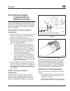
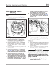
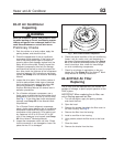
1. Uncover the electrical panel (see Fig. 1)byre-
moving the fasteners.
2. Check the wiring harness for movement that
could strain the electrical connections. Install
more clamps on the harness, if needed.
3. Check all the wiring for chafing, kinks, and dis-
colored insulation. Find the cause of any prob-
lems, then repair, replace, or reroute the wires,
as needed.
4. Check that all the relays are firmly seated in their
mounting plates.
5. Check the turn-signal flasher (if so equipped).
See Fig. 1. Make sure that the two male and
female connectors are firmly connected. Check
that the flasher fuse is firmly seated in its holder.
6. Check the cigarette lighter. Look inside the
socket for signs of overheating (discoloration,
melting) caused by misuse of the lighter socket.
7. Test the electric horn. If it does not work, check
the adjustment screw on the horn unit. Turn the
screw in or out, until the horn works. If the horn
still does not work, check the wiring to it. If the
wiring checks out okay, replace the horn.
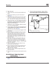
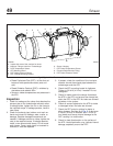
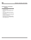
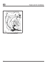
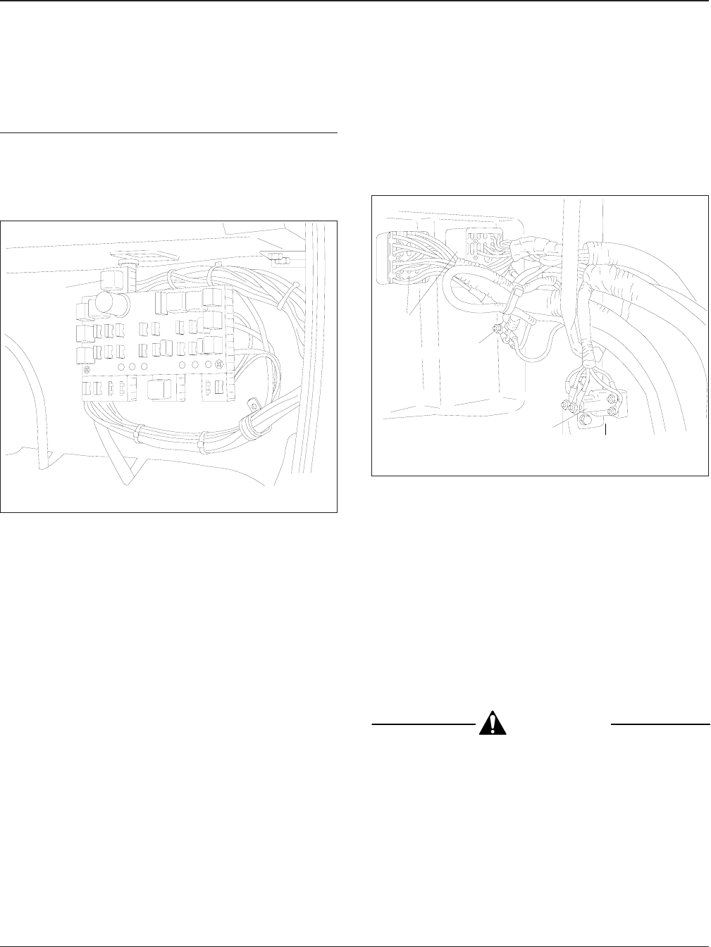
8. Check connectors on the right side of the fire-
wall, below the radiator surge tank. See Fig. 2.
Check the terminals for tightness, damage, and
corrosion or dirt.
9. Check the seven-way trailer cable plug at the
back of the cab. Make sure all the pins are tight
and free of dirt and grease.
Chassis
1. Check the main wiring harness. Check the wiring
insulation for damage from chafing or heat. Also
check for kinks. Reroute, repair, or replace the
wires as needed.
2. Check all the tie straps for breakage or damage.
Replace any broken or cracked tie straps.
CAUTION
Do not use flat-strip aluminum tie straps for hold-
ing electrical wiring. The sharp edges on these tie
straps may cause breaks in the wire insulation,
allowing the aluminum tie strap to make contact
with the wire. This could cause a short circuit and
damage to the wiring.
3. Check the temperature sending units on the
axles and transmission. Check for damaged
wires and loose connectors.
f540843
10/05/94
1
1. Flasher
Fig. 1, Under-Dash Electrical Panel
f540844
10/05/94
1
2
1
1. Electrical Connectors 2. Magnetic Switch
Fig. 2, Right Side of the Firewall
Electrical, Instruments, and Controls 54
Acterra Maintenance Manual, March 2000 54/1