


2-30
SPEC
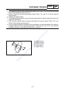
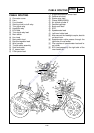
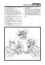
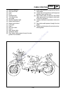
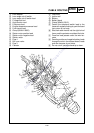
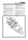
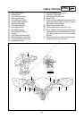
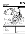
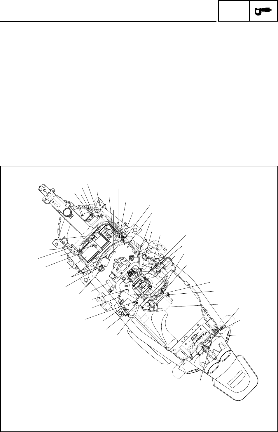
CABLE ROUTING
F Ignition coil lead passes under the cross
tube.
G Pass the throttle cable assembly through
wire guide.
H Locate the white tape of wire harness in the
holder.
I Clamp (90464-10800) the O
2
sensor lead.
J Clamp (90464-25803) the starter motor lead,
AC magneto lead, ISC (idle speed control)
valve lead, sensor module (MAQS) lead,
fuel injector lead and O
2
sensor lead.
K Seat lock cable passes through the hole of
seat bracket.
L Tail/brake light lead pass under the seat lock
cable.
M Turn signal light lead pass through the hole
at license bracket and combine with tail/
brake light lead.
N After combining the couplers, insert them
into the sockets at tail/brake light.
O Yellow mark to up of pipe 11.
P Assembly range of starter motor negative
lead terminal.
Q Torque: 7Nm (0.7m • kgf, 5.1ft • lbf).
R The terminal of battery negative pole (black
lead) shall tough the left surface of battery
box at least.
S Battery band buckles the rear side and then
front.
T The terminal of battery positive pole (red
lead) shall be aimed at the center of mark
“+” at footrest board.
U Torque: 5Nm (0.5m • kgf, 3.6ft • lbf).
V After combining the fuel injector coupler,
align the coupler (forward side) with the
clamp (inside).
F
6
5
9
8
q
7
i
o
p
R
a
E
G
I
V
e
t
K
N
O
w
L
M
H
A
0
J
D
B
A
3
2
1
U
T
Q
E
u
r
y
P
4
C
S
Downloaded from www.ScooterTime.net