7-41
-+
ELEC
EAS00804
4. The fuel level gauge fails to operate.
1. Fuel sender
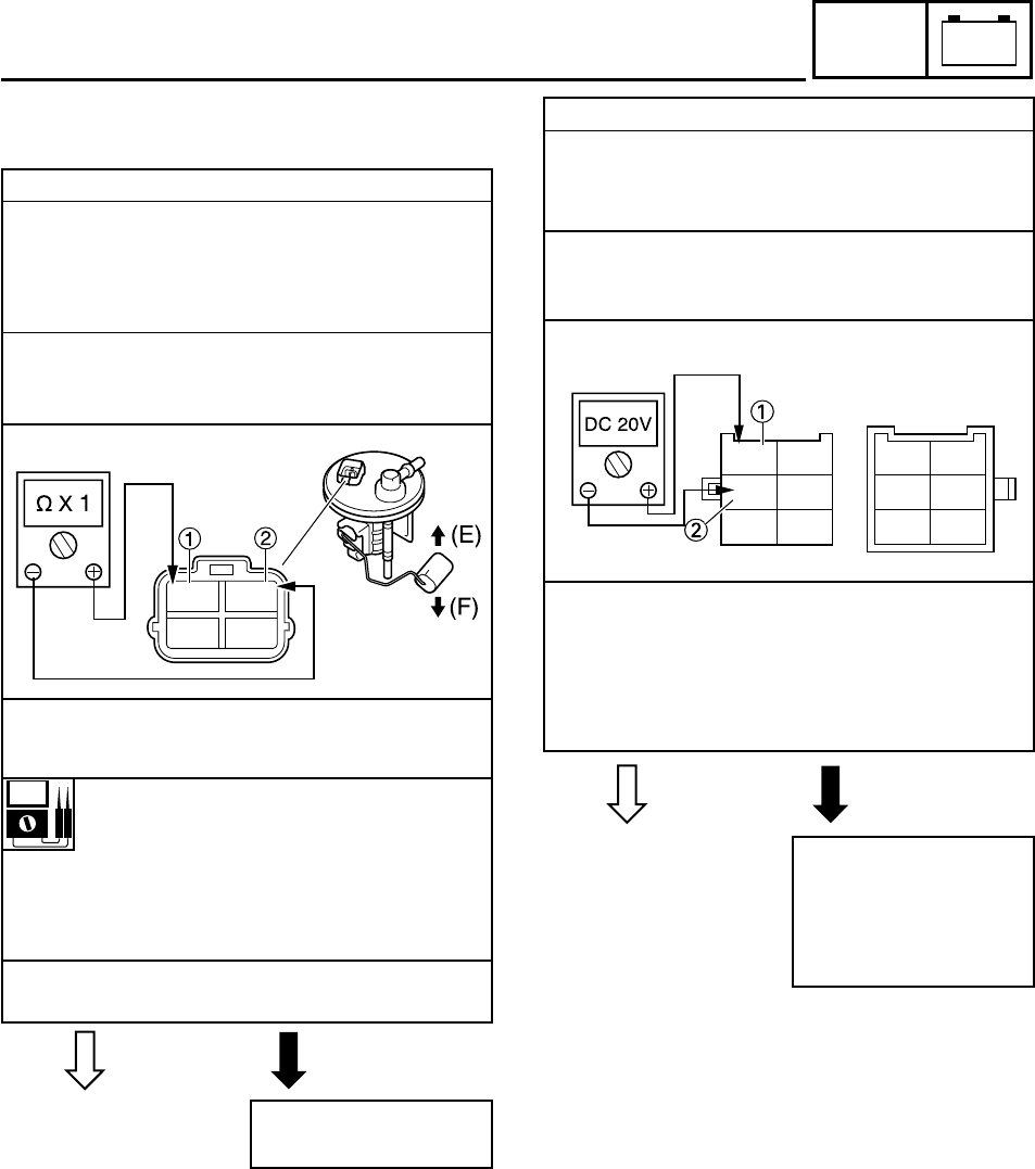
8 Remove the fuel pump from the fuel tank.
8 Connect the pocket tester (Ω × 1) to the fuel
sender coupler (wire harness side) as
shown.
Positive tester probe
JJ
JJ
J green
11
11
1
Negative tester probe
JJ
JJ
J black
22
22
2
8 Measure the fuel sender resistances.
Fuel sender resistance (up position
“F”)(
ΩΩ
ΩΩ
Ω
××
××
× 1)
4~10
ΩΩ
ΩΩ
Ω at 20°C (68°F)
Fuel sender resistance (down posi-
tion “E”)
(Ω(Ω
(Ω(Ω
(Ω
××
××
× 10)
90~100
ΩΩ
ΩΩ
Ω at 20°C (68°F)
8 Is the fuel sender OK?
YES NO
Replace the fuel
pump.
2. Voltage
8 Connect the pocket tester (DC 20 V) to the
meter light coupler (wire harness side) as
shown.
Positive tester probe
JJ
JJ
J brown
11
11
1
Negative tester probe
JJ
JJ
J black
22
22
2
8 Set the main switch to “ON”.
8 Measure the voltage (DC 12 V) of brown 1
on the meter light coupler (wire harness
side).
8 Is the voltage within specification?
YES NO
Check the wiring cou-
pler of the entire sig-
naling system.
Refer to “CIRCUIT
DIAGRAM”.
SIGNALING SYSTEM
G
R/B
B
L/B
Br
B
-
G
Lg
L
Br
B
-
G
Lg
L
Downloaded from www.ScooterTime.net


