


7-40
-+
ELEC
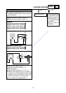
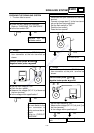
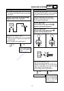
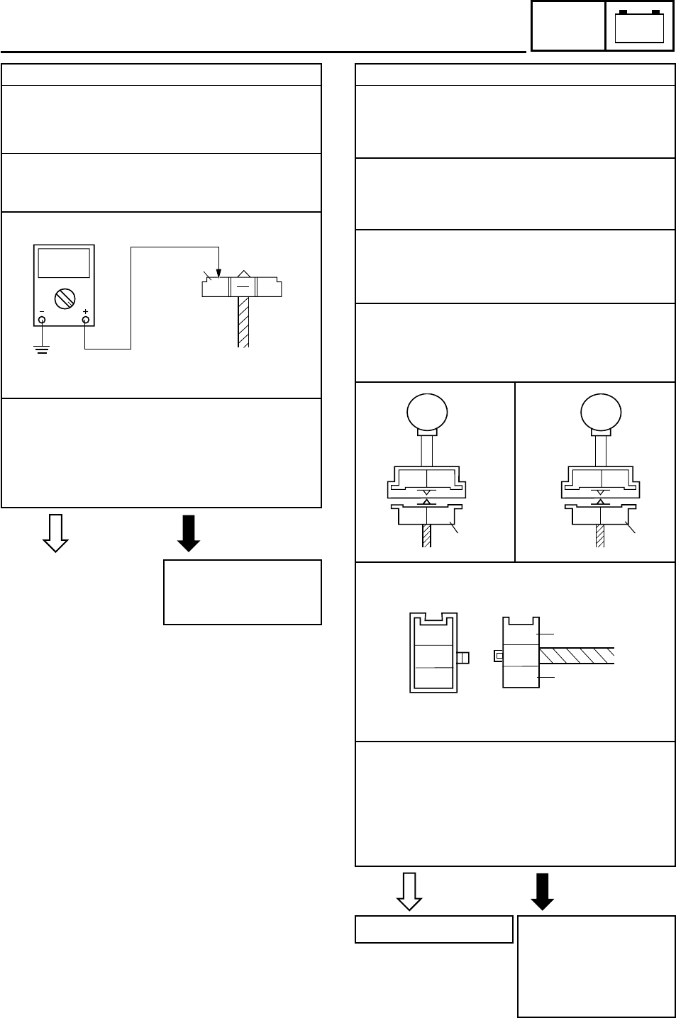
5. Voltage
8 Connect the pocket tester (DC 20 V) to the
turn signal relay coupler (wire harness side)
as shown.
Positive tester probe
JJ
JJ
J brown/white
11
11
1
Negative tester probe
JJ
JJ
J ground
8 Set the main switch to “ON”.
8 Measure the voltage (DC 12 V) on brown/
white 1 at the turn signal relay coupler (wire
harness side).
8 Is the voltage within specification?
YES NO
The turn signal relay is
faulty and must be re-
placed.
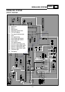
SIGNALING SYSTEM
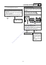
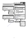
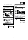
6. Voltage
8 Connect the pocket tester (DC 20 V) to the
turn signal light coupler or meter assembly
coupler (wire harness side) as shown.
A Left turn signal light (front and rear)
B Right turn signal light (front and rear)
C Turn signal indicator light
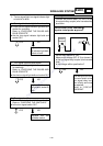
Left turn signal light
Positive tester probe
JJ
JJ
J chocolate
11
11
1
Negative tester probe
JJ
JJ
J ground
Right turn signal light
Positive tester probe
JJ
JJ
J dark green
22
22
2
Negative tester probe
JJ
JJ
J ground
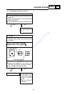
8 Set the main switch to “ON”.
8 Set the turn signal switch to “4” or “6”.
8 Measure the voltage (DC 12 V) of the choco-
late 1 or dark green 2 at the turn signal
light coupler (wire harness side).
8 Is the voltage within specification?
YES NO
This circuit is OK.
The wiring circuit from
the turn signal switch
to the turn signal light
coupler is faulty and
must be repaired.
1
2
B
Ch
B
Ch
B
Dg
B
Dg
A
B
C
Ch
Y
Dg
1
Ch
Y
Dg
2
DC20V
1
Br/W
Br
Downloaded from www.ScooterTime.net