


5B.25
Section 5B
EFI Fuel System
5B
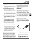
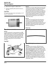
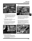
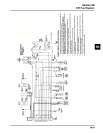
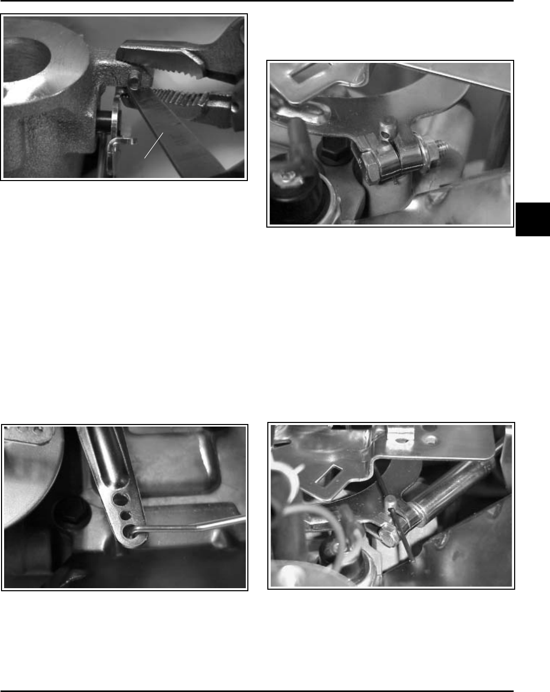
Figure 5B-39. Inserting Feeler Gauge (Engines
Without Stop Screw).
b. On engines with a stop screw, pivot the throttle
shaft and plate into the “Full Throttle” position,
so the tang of the throttle shaft plate is against
the end of the high-speed stop screw. See
Figure 5B-38. Temporarily clamp in this
position.
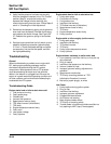
3. Rotate the governor lever and shaft
counterclockwise until it stops. Use only enough
pressure to hold it in that position.
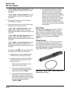
4. Check how the end of the throttle linkage aligns
with the bushing hole in the governor lever. See
Figure 5B-40. It should fall in the center of the
hole. If it doesn’t, perform the adjustment
procedure as follows.
If not already installed, position the governor lever
on the cross shaft, but leave the clamping screw
loose.
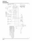
Feeler Gauge
Figure 5B-40. Throttle Link in Center of Hole.
B. Setting the Initial Adjustment
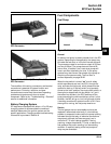
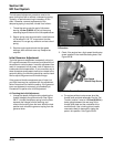
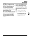
1. Check the split where the clamping screw goes
through the governor lever. See Figure 5B-41.
There should be a gap of at least 1/32". If the tips
are touching and there is no gap present, the
lever should be replaced.
Figure 5B-41. Checking ‘‘Split’’ of Clamp.
2. Follow the instructions in Step 2 of ‘‘Checking the
Initial Adjustment,’’ then reattach the throttle
linkage to the governor lever with the bushing clip.
It is not necessary to reattach the damper or
governor springs at this time.
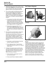
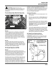
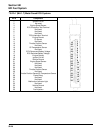
3. Insert a nail into the hole in the top of the cross
shaft. Using light pressure, rotate the governor
shaft counterclockwise as far as it will turn, then
torque the hex. nut on the clamping screw to
9.9 N·m (88 in. lb.). See Figure 5B-42. Make sure
that the governor arm has not twisted up or down
after the nut has been tightened.
Figure 5B-42. Adjusting Governor Shaft.