


5.3
Section 5
Fuel System and Governor
5
NOTE: On most models, the pulse line is
connected to a fitting on the crankcase,
while on early models, it is connected to
the valve cover.
4. Install the new fuel pump using the hex. flange
screws. Torque the hex. flange screws to 2.3 N·m
(20 in. lb.).
NOTE: Make sure the orientation of the new
pump is consistent with the removed
pump. Internal damage may occur if
installed incorrectly.
5. Connect the pulse line to the pulse fitting.
6. Connect the fuel lines to the inlet and outlet
fittings.
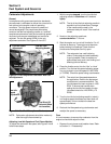
Replacing the Mechanical Pump
The mechanical pump is an integral part of the valve
cover assembly and not serviced separately. See
Figure 5-2.
1. Disconnect the fuel lines from the inlet and outlet
fittings.
2. Follow the procedure for replacing the valve cover
(Sections 9 and 11).
3. Reconnect the fuel lines to the inlet and outlet
fittings.
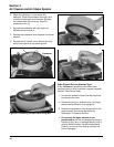
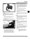
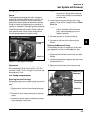
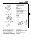
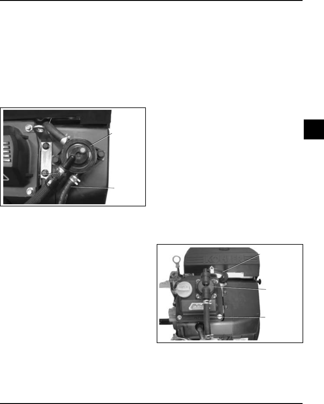
Figure 5-1. Pulse Style Fuel Pump.
Performance
Minimum fuel delivery rate must be 7.5 L/hr. (2 gal./hr.)
with a pressure at 0.3 psi and a fuel lift of 18 in. from
carburetor inlet. A 1.3 L/hr. (0.34 gal./hr.) fuel rate must
be maintained at 5 Hz.
Fuel Pump - Replacement
Replacing the Pulse Fuel Pump
Replacement pumps are available through your source
of supply. To replace the pulse pump follow these
steps.
1. Disconnect the fuel lines from the inlet and outlet
fittings.
2. Remove the hex. flange screws securing the fuel
pump.
3. Remove the pulse line that connects the pump to
the crankcase or valve cover.
Fuel Pump
General
These engines are equipped with either a pulse or
mechanical fuel pump. See Figures 5-1 and 5-2. The
pumping action is created by either the oscillation of
positive and negative pressures within the crankcase
through a hose, or by direct lever/pump actuation off
rocker arm movement. The pumping action causes the
diaphragm on the inside of the pump to pull fuel in on
its downward stroke and to push it into the carburetor
on its upward stroke. Internal check valves prevent
fuel from going backward through the pump.
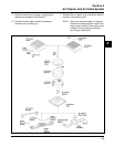
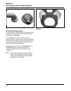
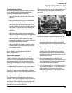
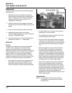
Figure 5-2. Mechanical Fuel Pump.
Pulse Line
Outlet Line (to Carburetor)
Pulse Fuel
Pump
Inlet Line
Outlet Line (to
Carburetor)
Mechanical
Fuel Pump
Inlet Line