


5B.17
Section 5B
EFI Fuel System
5B
8. Thoroughly clean the area around and including
the throttle body/manifold and the injectors.
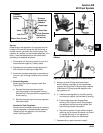
9. Disconnect the throttle linkage and damper spring
from the throttle lever. Disconnect the TPS lead
from the harness.
10. Remove the manifold mounting bolts and
separate the throttle body/manifold from the
engine leaving the TPS, fuel rail, air baffle,
injectors and line connections intact. Discard the
old gaskets.
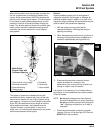
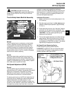
11. Position the manifold assembly over an
appropriate container and turn the key switch
“on” to activate the fuel pump and pressurize the
system. Do not turn switch to “start” position.
12. If either injector exhibits leakage of more than two
to four drops per minute from the tip, or shows
any sign of leakage around the outer shell, turn
the ignition switch off and replace injector as
follows.
13. Depressurize the fuel system following the
procedure in the fuel warning on page 5B.2.
Remove the two fuel rail mounting screws.
14. Clean any dirt accumulation from the sealing/
mounting area of the faulty injector(s) and
disconnect the electrical connector(s).
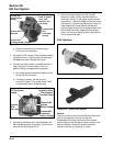
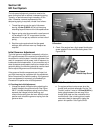
15. Pull the retaining clip off the top of the injector(s)
and remove from manifold.
16. Reverse the appropriate procedures to install the
new injector(s) and reassemble the engine. Use
new O-Rings any time an injector is removed
(new replacement injectors include new O-Rings).
Lubricate O-Rings lightly with oil. Torque the fuel
rail and blower housing mounting screws to
3.9 N·m (35 in. lb.), and the intake manifold and
air cleaner mounting screws to 9.9 N·m
(88 in. lb.).
Injector problems due to dirt or clogging are generally
unlikely, due to the design of the injectors, the high fuel
pressure, and the detergent additives in the gasoline.
Symptoms that could be caused by dirty/clogged
injectors include rough idle, hesitation/stumble during
acceleration, or triggering of fault codes related to fuel
delivery. Injector clogging is usually caused by a
buildup of deposits on the director plate, restricting the
flow of fuel, resulting in a poor spray pattern. Some
contributing factors to injector clogging include higher
than normal operating temperatures, short operating
intervals, and dirty, incorrect, or poor quality fuel.
Cleaning of clogged injectors is not recommended;
they should be replaced. Additives and higher grades
of fuel can be used as a preventative measure if
clogging has been a problem.
Ignition System
General
A high voltage, solid state, battery ignition system is
used with the EFI system. The ECU controls the
ignition output and timing through transistorized control
of the primary current delivered to the coils. Based on
input from the speed sensor, the ECU determines the
correct firing point for the speed at which the engine is
running. At the proper instant, it releases the flow of
primary current to the coil. The primary current
induces high voltage in the coil secondary, which is
then delivered to the spark plug. Each coil fires every
revolution, but every other spark is “wasted.”
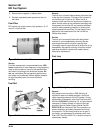
Service
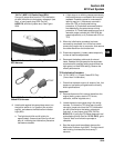
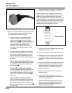
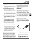
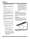
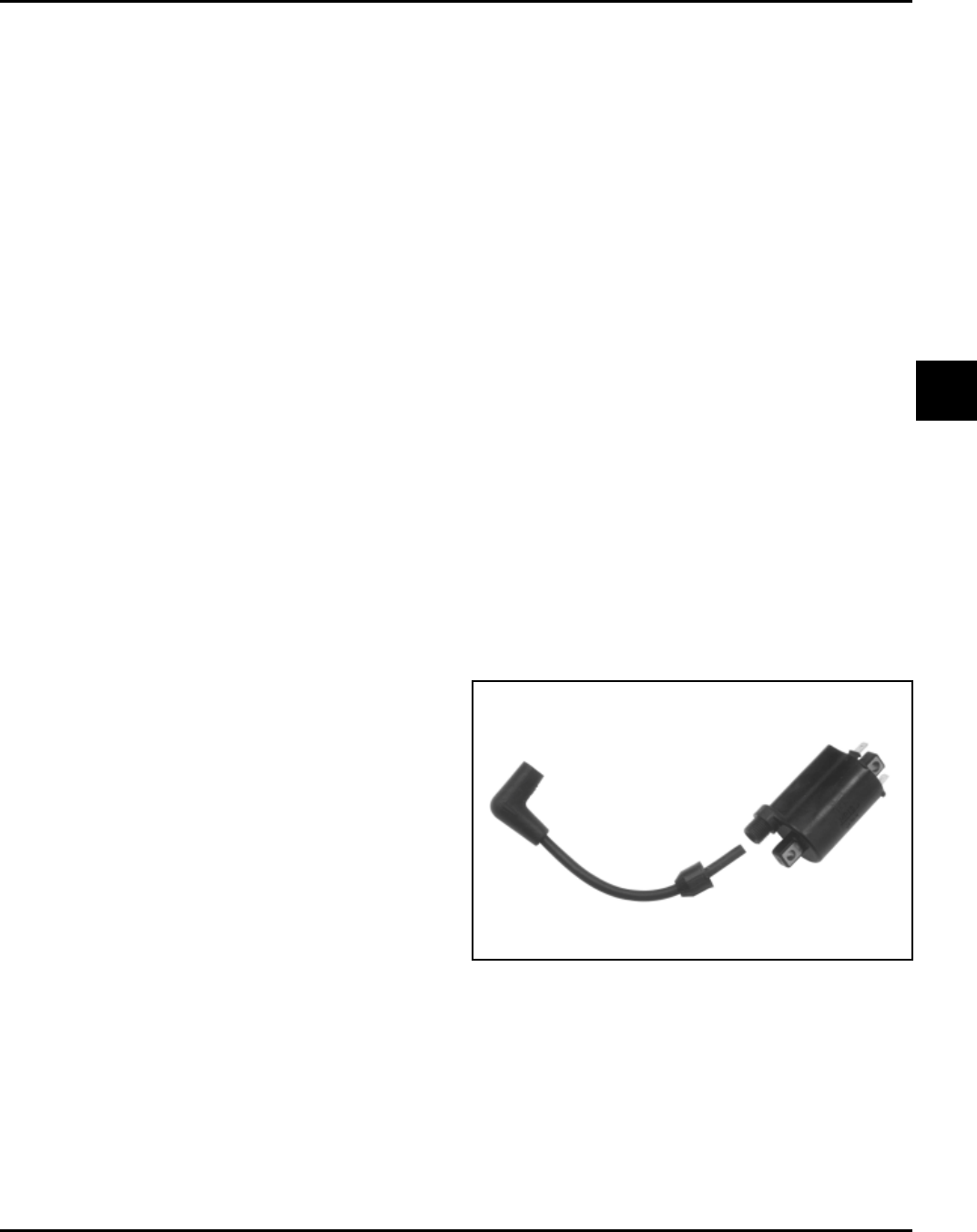
Except for removing the spark plug lead by
unscrewing it from the secondary tower (see Figure
5B-22), no coil servicing is possible. If a coil is
determined to be faulty, replacement is necessary. An
ohmmeter may be used to test the wiring and coil
windings.
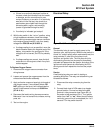
Figure 5B-22. Ignition Coil.
NOTE: Do not ground the coils with the ignition ‘‘on,’’
as they may overheat or spark.
Testing
1. Disconnect the main harness connector from
ECU.
“35 Pin” (MA 1.7) Metal-Cased ECU: Locate
pins #1 and #19 in the 35 pin connector. See
page 5B.28.