


5.11
Section 5
Fuel System and Governor
5
General
The governed speed setting is determined by the
position of the throttle control. It can be variable or
constant, depending on the engine application.
Initial Adjustment
NOTE: EFI engines require a special initial
adjustment procedure, which is covered in
subsection 5B. Refer to “Initial Governor
Adjustment” in that section for setting the
governor on EFI-equipped engines.
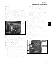
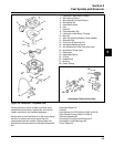
Procedure – Carburetor Equipped Engines
Make this adjustment whenever the governor arm is
loosened or removed from the cross shaft. See Figure
5-9 and adjust as follows:
1. Make sure the throttle linkage is connected to the
governor arm and the throttle lever on the
carburetor.
2. Loosen the hex. nut holding the governor lever to
the cross shaft.
3. Move the governor lever toward the carburetor as
far as it will move (wide open throttle) and hold in
this position.
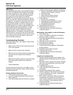
4. Insert a nail into the hole on the cross shaft and
rotate the shaft counterclockwise as far as it will
turn, then tighten hex. nut securely.
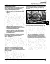
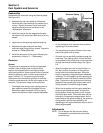
Sensitivity Adjustment
Governor sensitivity is adjusted by repositioning the
governor spring in the holes of the governor lever. If
speed surging occurs with a change in engine load,
the governor is set too sensitive. If a big drop in speed
occurs when normal load is applied, the governor
should be set for greater sensitivity. See Figure 5-10
and adjust as follows:
1. To increase the sensitivity, move the spring closer
to the governor cross shaft.
2. To decrease the sensitivity, move the spring away
from the governor cross shaft.
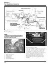
Figure 5-10. Governor Sensitivity Adjustments.
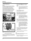
High Speed (RPM) Adjustment (Refer to Figure 5-11.)
1. With the engine running, move the throttle control
to fast. Use a tachometer to check the RPM
speed.
2. Loosen the lock nut on high speed adjusting screw.
Turn the screw outward to decrease, or inward to
increase the RPM speed. Check RPM with a
tachometer.
3. When the desired RPM speed is obtained,
retighten the lock nut.
NOTE: When the throttle and choke control cables are
routed side-by-side, especially under a single
clamp, there must be a small gap between the
cables to prevent internal binding. After the
high-speed setting has been completed, check
that there is a gap of at least 0.5 mm
(0.020 in.) between the control cables.