11.15
Section 11
Reassembly
11
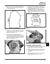
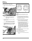
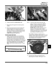
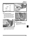
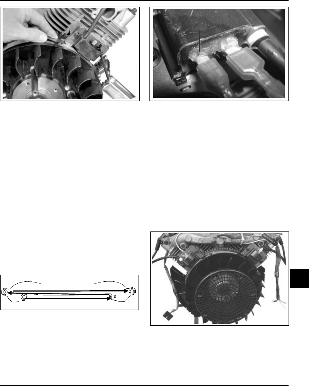
Figure 11-50. Setting Ignition Module Air Gap.
6. Torque the screws to 4.0 N·m (35 in. lb.).
7. Repeat steps 4 through 6 for the other ignition
module.
8. Rotate the flywheel back and forth checking for
clearance between the magnet and ignition
modules. Make sure the magnet does not strike
the modules. Check the gap with a feeler gauge
and readjust if necessary. Final Air Gap:
0.280/0.330 mm. (0.011/0.013 in.).
Install Intake Manifold
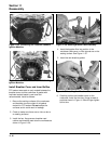
1. Install the intake manifold and new gaskets or
O-Rings (plastic manifold), with wiring harness
attached, to the cylinder heads. Slide any wiring
harness clips onto the appropriate bolts before
installing. Make sure the gaskets are in the proper
orientation. Torque the four screws in two stages,
first to 7.4 N·m (66 in. lb.), then to 9.9 N·m
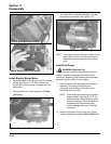
(88 in. lb.), using the sequence shown in Figure
11-51.
1
2
3
4
Sealant
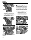
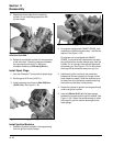
Figure 11-51. Intake Manifold Torque Sequence.
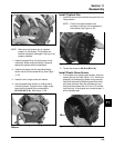
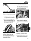
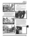
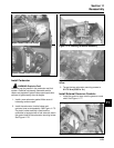
Figure 11-52. Sealant Applied to Terminals.
NOTE: If the wires were disconnected from the
ignition modules on engines with SMART-
SPARK
™
, reattach the leads and seal the
base of the terminal connectors with GE/
Novaguard G661 (Kohler Part No.
25 357 11-S) or Fel-Pro Lubri-Sel dielectric
compound. The beads should overlap
between the terminals* to form a solid bridge
of compound. See Figure 11-52. Do not put
any compound inside the terminals.
*The 24 584 15-S ignition modules have a
separator barrier between the terminals. On these
modules, seal the base of the terminals, but it is
not necessary to have overlapping beads of
sealant between the connections.
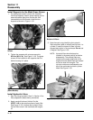
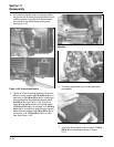
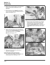
Figure 11-53. Routing of Wiring Harness.
2. Connect the kill lead to the tab terminal on
standard ignition modules. See Figure 11-54.


