


8.6
Section 8
Electrical System and Components
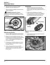
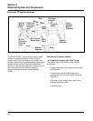
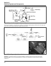
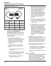
Figure 8-6. Capacitive Discharge Ignition System with Spark Advance.
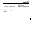
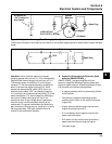
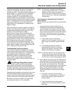
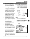
Power
Source
Pulse
Generator
Reset
Circuit
B+ (12 VDC)
Red
Yellow
To
Semi-Conductor
Switch
Comparator
Delay
Circuit
Charge
Pump
Conditioning
Circuit
V+ (7.2V)
Brown
From
Input
Coil
Green
or Black
Figure 8-7. Block Diagram - Spark Advance Module.
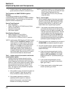
Operation: The ignition module for this system operates in the same fashion as the fixed timing module,
except the trigger circuit for the semiconductor (L2, Figure 8-5) is replaced by the spark advance module
(Figure 8-7).
The timing of the spark is controlled by the location of the flywheel magnet group as referenced to the engine top
dead center and the delay created by the spark advance module.
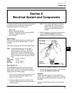
Key Switch or ‘‘Off’’
Position of Key Switch
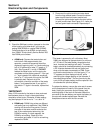
Spark Advance Module
12 Volt Battery
Spark Plug
Ignition Module
Flywheel
Magnet
0.28/0.33 mm
(0.011/0.013 in.)
Air Gap
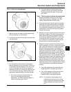
Spark
Plug
Green
Red
White