


5B.20
Section 5B
EFI Fuel System
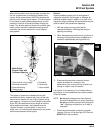
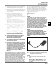
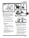
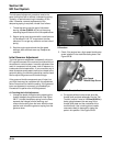
1. Connect the black hose of Kohler pressure tester
(SPX Part No. KO3217-4), to the test valve in the
fuel rail. Route the clear hose into a portable
gasoline container or the equipment fuel tank.
2. Turn on the key switch to activate the pump and
check the system pressure on the gauge. If
system pressure of 39 psi ± 3 is observed, the
relay, fuel pump, and regulator are working
properly. Turn the key switch off and depress the
valve button on the tester to relieve the system
pressure.
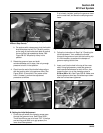
a. If the pressure is too high, and the regulator is
outside the tank (just down line from the
pump), check that the return line from the
regulator to the tank is not kinked or blocked.
If the return line is good, replace the regulator
(see ‘‘Regulator Service’’ on page 5B.21).
b. If the pressure is too low, install in-line ‘‘T’’
(SPX Part No. KO3217-8) between the pump
and regulator and retest the pressure at that
point. If it is too low there also, replace the fuel
pump.
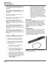
3. If the pump did not activate (step 2), disconnect
the plug from the fuel pump. Connect a DC
voltmeter across the terminals in the plug, turn on
the key switch and observe if a minimum of 7
volts is present. If voltage is between 7 and 14,
turn key switch off and connect an ohmmeter
between the terminals on the pump to check for
continuity.
a. If there was no continuity between the pump
terminals, replace the fuel pump.
b. If the voltage was below 7, test the wiring
harness and relay as covered in the ‘‘Electrical
Relay’’ section.
4. If voltage at the plug was good, and there was
continuity across the pump terminals, reconnect
the plug to the pump, making sure you have a
good connection. Turn on the key switch and
listen for the pump to activate.
a. If the pump starts, repeat steps 1 and 2 to
verify correct pressure.
b. If the pump still does not operate, replace it.
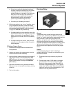
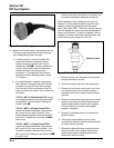
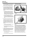
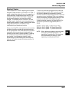
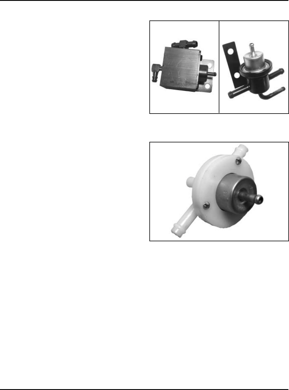
Figure 5B-28. Internal Fuel Pressure Regulator.
General
The fuel pressure regulator assembly maintains the
required operating system pressure of 39 psi ± 3. A
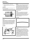
rubber-fiber diaphragm (see Figure 5B-29) divides the
regulator into two separate sections; the fuel chamber
and the pressure regulating chamber. The pressure
regulating spring presses against the valve holder (part
of the diaphragm), pressing the valve against the valve
seat. The combination of atmospheric pressure and
regulating spring tension equals the desired operating
pressure. Any time the fuel pressure against the
bottom of the diaphragm exceeds the desired (top)
pressure, the valve opens, relieving the excess
pressure, returning the excess fuel back to the tank.
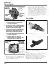
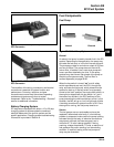
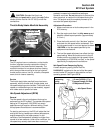
Fuel Pressure Regulator
Figure 5B-27. External Fuel Pressure Regulators
with Base.