


8.11
Section 8
Electrical System and Components
8
terminal of the ground lead or the ground
screw/bolt. Check the voltage with the key
switch in both the “START” and “RUN”
positions. A minimum of 7.25 volts must be
present.
a. If correct voltage is not measured, connect
black voltmeter lead directly to the negative
(-) post of the battery and test voltage again
in both key positions. If correct voltage is
now indicated, check the ground circuit
connections. If the ground screw/bolt or any
other fasteners in the ground circuit are
black (oxide-coated), replace them with
zinc plated (silver colored) fasteners.
b. If correct voltage is still not indicated, check
the harness connector terminal for a good
connection and crimp to the lead. Then
trace the power source circuit back through
the harness, key switch, etc., looking for
any poor connections, or faulty circuits.
2. Disconnect all of the SAM leads, isolating it
from the engine. Test the SAM with tester
25 761 21-S, following the instructions following
or use TT481-A provided with the tester. If the
SAM tests bad, replace it.
3. Reattach the SAM leads, verifying a snug fit at
the ignition module terminals. If any
connections do not feel snug, disconnect the
lead, lightly pinch the female terminal with a
pliers, and recheck the fit.
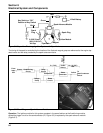
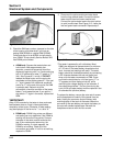
4. Seal the base of the ignition module
connections with GE/Novaguard G661 (Kohler
Part No. 25 357 11-S) or Fel-Pro Lubri-Sel
dielectric compound. The beads should overlap
between the two connections
†
to form a solid
bridge of compound. Do not put any compound
inside the connectors.
†
The 24 584 15-S ignition modules have a
separator/barrier between the terminals. On
these modules, seal the base of the terminal
if any portion of it is exposed, but it is not
necessary to have overlapping beads of
sealant between the connections.
5. Test for spark (Test 2) to be sure the system is
working, before you reinstall the blower
housing. If there is still a spark problem on one
side, replace that ignition module and recheck
spark.
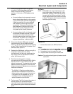
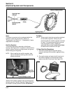
To Test –
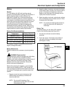
NOTE: SAM must be at room temperature (to the
touch) when tested. Disconnect ALL of the
SAM leads, isolating it from the main wiring
harness and the ignition module(s). Testing
may be performed with the module mounted
or loose. The figures show the part removed
from the engine for clarity.
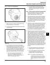
Figure 8-10.
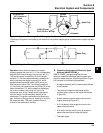
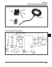
1. Connect the tester to the SAM as follows:
Attach:
A. The yellow tester lead to the long yellow module lead.
B. The brown tester lead to the long brown module lead.
C. The red tester lead to the red module lead.
D. The green tester lead to the green module lead.
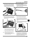
Caution: Do not allow the alligator clip leads to touch
each other.
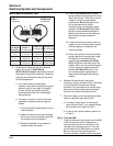
Figure 8-11.