


10.12
Section 10
Inspection and Reconditioning
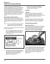
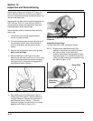
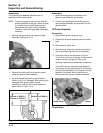
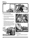
Figure 10-13. Removing Governor Gear.
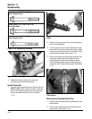
2. Remove the locking tab thrust washer located
under the governor gear assembly.
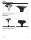
3. Carefully inspect the governor gear shaft and
replace it only if it is damaged. After removing the
damaged shaft, press or lightly tap the
replacement shaft into the closure plate to the
depth shown in Figure 10-14.
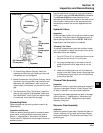
Reassembly
1. Install the locking tab thrust washer on the
governor gear shaft with the tab down.
2. Position the regulating pin within the governor
gear/flyweight assembly and slide both onto the
governor shaft.
Oil Pump Assembly
Disassembly
1. Remove the two hex. flange screws.
2. Remove the oil pump assembly from the closure
plate.
3. Remove the oil pump rotor.
4. Remove the oil pickup by unhooking the locking
clip, and pulling it free from the oil pump body.
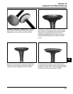
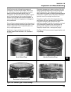
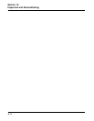
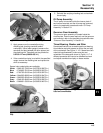
5. If the relief valve is like that shown in Figure
10-15, drive out the pin to remove the oil pressure
relief valve piston and spring. Refer to the
following inspection and reassembly procedures.
If the relief valve is a one-piece style, staked to
the oil pump housing (See Figure 10-16) removal
should not be attempted, nor is internal servicing
possible. If a problem with the relief valve is
encountered, the oil pump should be replaced.
Disassembly
The governor gear must be replaced once it is
removed from the closure plate.
NOTE: The governor gear is held onto the shaft by
small molded tabs in the gear. When the gear
is removed from the shaft, these tabs are
destroyed and the gear must be replaced.
Therefore, remove the gear only if absolutely
necessary.
1. Remove the regulating pin and governor gear
assembly. See Figure 10-13.
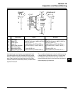
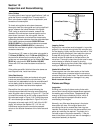
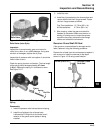
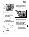
Figure 10-14. Governor Shaft Press Depth.
Gear Shaft
34.0 mm (1.3386 in.)
33.5 mm (1.3189 in.)
19.40 mm (0.7638 in.)
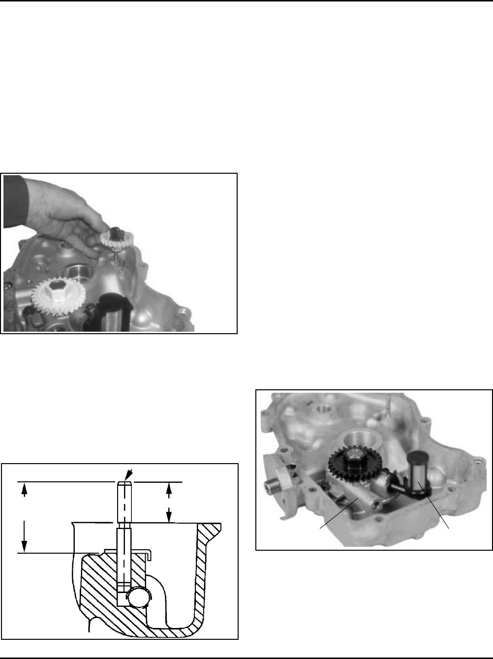
Figure 10-15. Oil Pump, Oil Pickup, and Relief Valve
(Original Style).
PickupRelief Valve