


5A.7
Section 5A
LPG Fuel Systems
5A
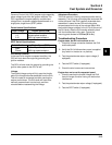
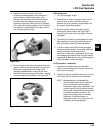
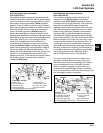
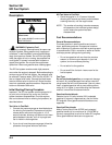
3. Insert a 0.025 mm (0.001 in.) feeler gauge
between the side of the stop collar and the
carburetor housing, then check or set the position
of the stop collar. The head of the mounting screw
must be in contact with the carburetor boss from
the back (hose/fitting) side, preventing any further
rotation over center. Set or adjust the stop collar
as required. See Figure 5A-12.
Figure 5A-12. Adjusting/Setting Stop Collar.
4. Tighten the screw securely.
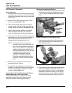
NOTE: After the idle speed clamp bracket and the
high speed stop collar positions have been
set, check that the throttle shaft pivots freely
without binding or restriction.
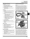
Throttle Linkage Clamp Bracket Position
Carburetor must be assembled to engine with linkage
attached to set this position.
1. The throttle linkage clamp bracket should be
positioned as shown in Figure 5A-13 on the idle
speed clamp bracket side of the throttle shaft.
Figure 5A-13. Throttle Linkage Clamp Bracket
Position.
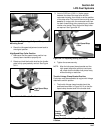
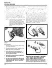
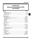
Figure 5A-10. Tightening Idle Speed Clamp
Mounting Screw.
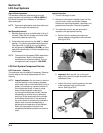
4. Reset the idle speed adjustment screw back to
the original position.
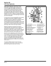
High Speed/Stop Collar Position
1. Make sure the idle speed clamp position has
already been checked or properly set.
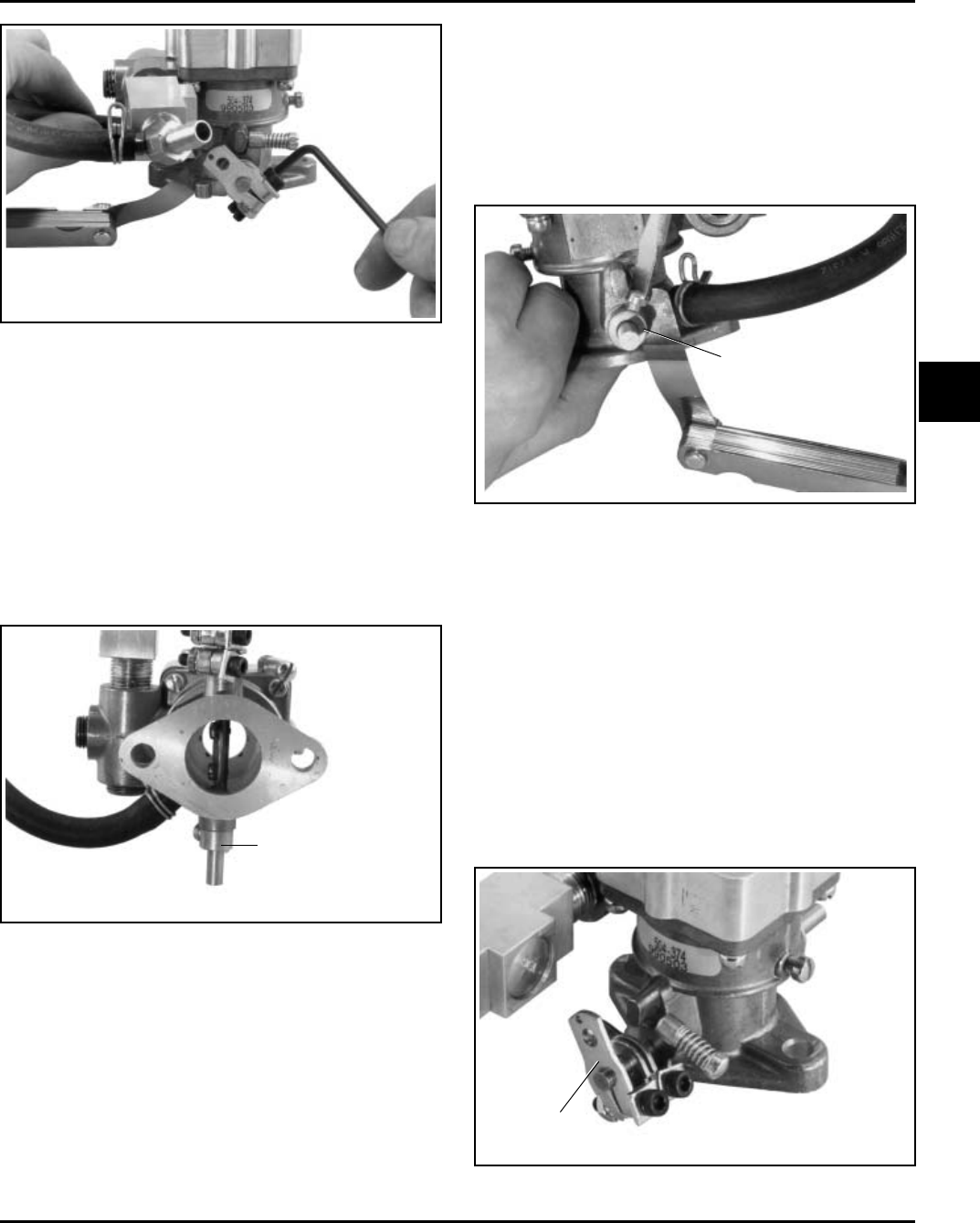
2. Rotate and hold the throttle shaft so the throttle
plate is fully open/perfectly vertical. See Figure
5A-11.
Figure 5A-11. Full Throttle Position.
High Speed Stop
Collar
High Speed Stop
Collar
Throttle
Linkage
Clamp Bracket