


11.23
Section 11
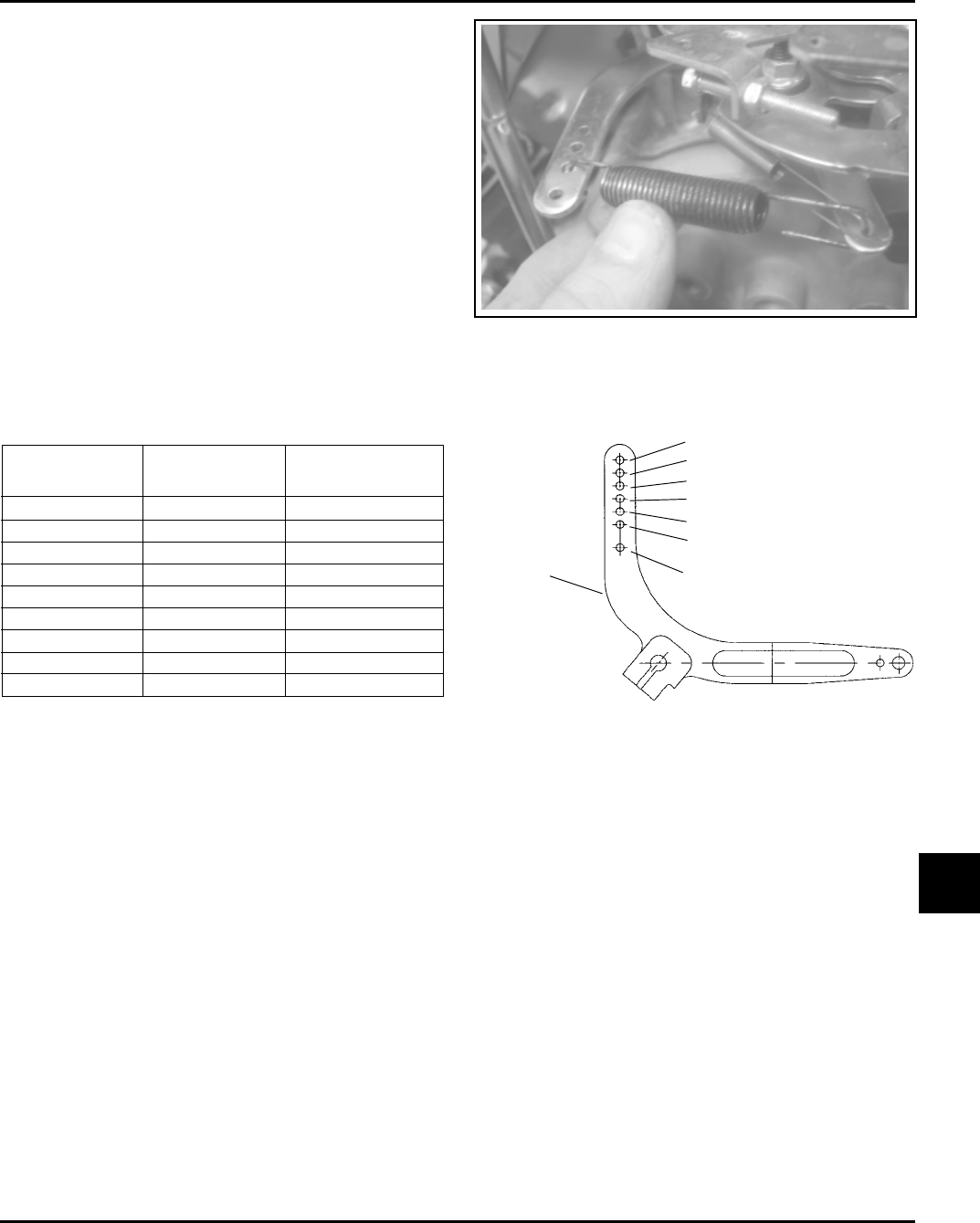
Reassembly
11
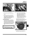
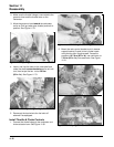
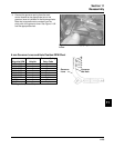
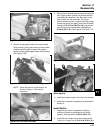
Figure 11-82. Connecting Spring to Governor
Lever.
3. Connect the governor spring from the main
control bracket to the appropriate hole in the
governor lever as indicated in the following charts.
Note that hole positions are counted from the
pivot point of the governor lever. See Figure 11-82
and the appropriate chart.
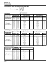
6 mm Governor Lever and Hole Position/RPM Chart
3801-4000
3601-3800
3451-3600
3301-3450
3101-3300
2951-3100
2800-2950
3750*
3150*
High Idle RPM
Gov. Lever
Hole No.
Governor Spring
Color Code
5
4
3
2
4
3
2
3
3
Clear
Clear
Clear
Clear
Purple
Purple
Purple
Clear
Purple
*5% Regulation (others 10%)
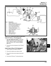
6
5
4
3
2
1
Governor
Idle Hole
Governor
Lever