


5A.11
Section 5A
LPG Fuel Systems
5A
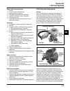
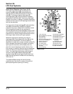
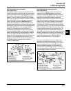
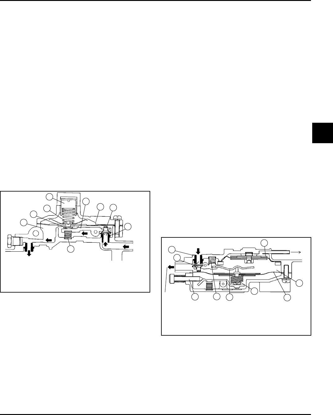
Nikki Regulator Primary Chamber
(See Figure 5A-21)
The primary chamber reduces the high pressure fuel
flow from the tank and vaporizer down to approximately
4 psi. Fuel flowing from the vaporizer enters the inlet of
the regulator under approximately 76 kPa (11 psi) of
pressure. There it is delivered to the primary chamber
(3) through the clearance between the primary valve (1)
and valve seat (2). As fuel continues to flow and the
primary chamber approaches 29 kPa (4 psi), the
primary diaphragm (4) overcomes the tension of the
diaphragm spring (5). As the diaphragm (4) and contact
button (6) move up, the primary lever spring (8) pushes
the primary lever (7) up, in turn closing the primary
valve (1) and stopping the flow of fuel. As fuel is
consumed and the pressure in the primary chamber
drops below 29 kPa (4 psi), the diaphragm spring (5)
tension will be greater than the fuel pressure, causing
the primary diaphragm (4) to be pushed down. This
causes the contact button (6), to push the primary lever
(7) down, in turn opening the primary valve (1) and
admitting more fuel. In this manner, the pressure within
the primary chamber is maintained at a relatively
constant 29 kPa (4 psi).
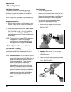
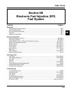
Nikki Regulator Secondary Chamber
(See Figure 5A-22)
The secondary chamber further reduces the fuel
pressure from the 29 kPa (4 psi) of the primary
chamber to near 0 kPa (0 psi) pressure, to prevent
excessive fuel flow to the carburetor. Fuel enters the
secondary chamber (13) through the clearance
between the secondary valve (11) and the valve seat
(12). While the engine is operating, and fuel is being
drawn from the secondary chamber, the secondary
diaphragm (14) is raised by atmospheric pressure,
simultaneously lifting the secondary valve lever (16),
opening the secondary valve (11), allowing fuel to flow.
When the engine is running at idle, there may not be
enough vacuum created in the carburetor venturi to
overcome the tension of the secondary diaphragm
spring (15), and the secondary diaphragm cannot open
the valve. Under those conditions, the idle adjusting
screw (18), and balance spring (19) are used to apply
just enough pressure on the diaphragm (14) to
maintain sufficient fuel flow for idle operation.
The vacuum lock-off mechanism is located in the
secondary chamber. When the engine is running,
manifold vacuum above the diaphragm (17) draws it
up, so the secondary valve can function normally.
When the engine is stopped, manifold vacuum is
terminated, and the diaphragm relaxes and pushes
down on the secondary valve lever, preventing any fuel
flow or leakage through the regulator.
11) Secondary Valve 16) Secondary Valve Lever
12) Secondary Valve Seat 17) Vacuum Lock-Off
13) Secondary Chamber Diaphragm
14) Secondary Diaphragm 18) Idle Adjust Screw
15) Secondary Diaphragm Spring 19) Balance Spring
From Primary
Chamber
13
14
19
16
15
To
Carburetor
11
To Intake
Manifold
17
18
12
Figure 5A-22. Secondary Chamber.
Figure 5A-21. Primary Chamber.
1) Primary Valve 6) Contact Button
2) Primary Valve Seat 7) Primary Valve Lever
3) Primary Chamber 8) Primary Lever Spring
4) Primary Diaphragm 9) Primary Pressure
5) Primary Diaphragm Spring Adjustment
To Secondary Chamber
8
3
6
5
9
7
4
1
2
Fuel
Inlet