


11.12
Section 11
Reassembly
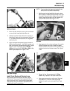
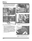
Figure 11-41. Torquing Cylinder Head Fasteners.
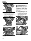
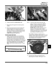
Figure 11-42. Cylinder Head Fastener Torque
Sequence.
Heads secured with mounting studs, nuts, and
washers:
2. If all of the studs were left intact, go to Step 6. If
any studs were disturbed or removed, install new
studs as described in Step 3. Do not use/reinstall
any loosened or removed studs.
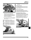
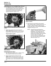
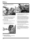
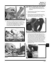
3. Install new mounting stud(s) into the crankcase.
a. Thread and lock two of the mounting nuts
together on the smaller diameter threads.
b. Thread the opposite end of the stud, with the
preapplied locking compound, into the
crankcase, until the specified height from the
crankcase surface is achieved. See Figure
11-43. When threading in the studs, use a
steady tightening motion without interruption
until the proper height is obtained. Otherwise,
the frictional heat from the engaging threads
may cause the locking compound to set up
prematurely.
The studs closest to the lifters must have an exposed
height of 75 mm (2 15/16 in.).
The studs furthest from the lifters must have an
exposed height of 69 mm (2 3/4 in.).
c. Remove the nuts and repeat the procedure as
required.
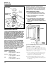
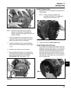
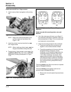
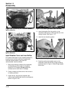
Figure 11-40. Always Use New Head Gaskets.
NOTE: Match the numbers embossed on the
cylinder heads and crankcase. See
Figure 11-36.
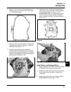
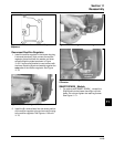
3. Install the cylinder head and start the four new
hex. flange screws.
NOTE: When installing cylinder heads, new hex.
flange screws should always be used.
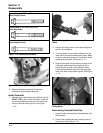
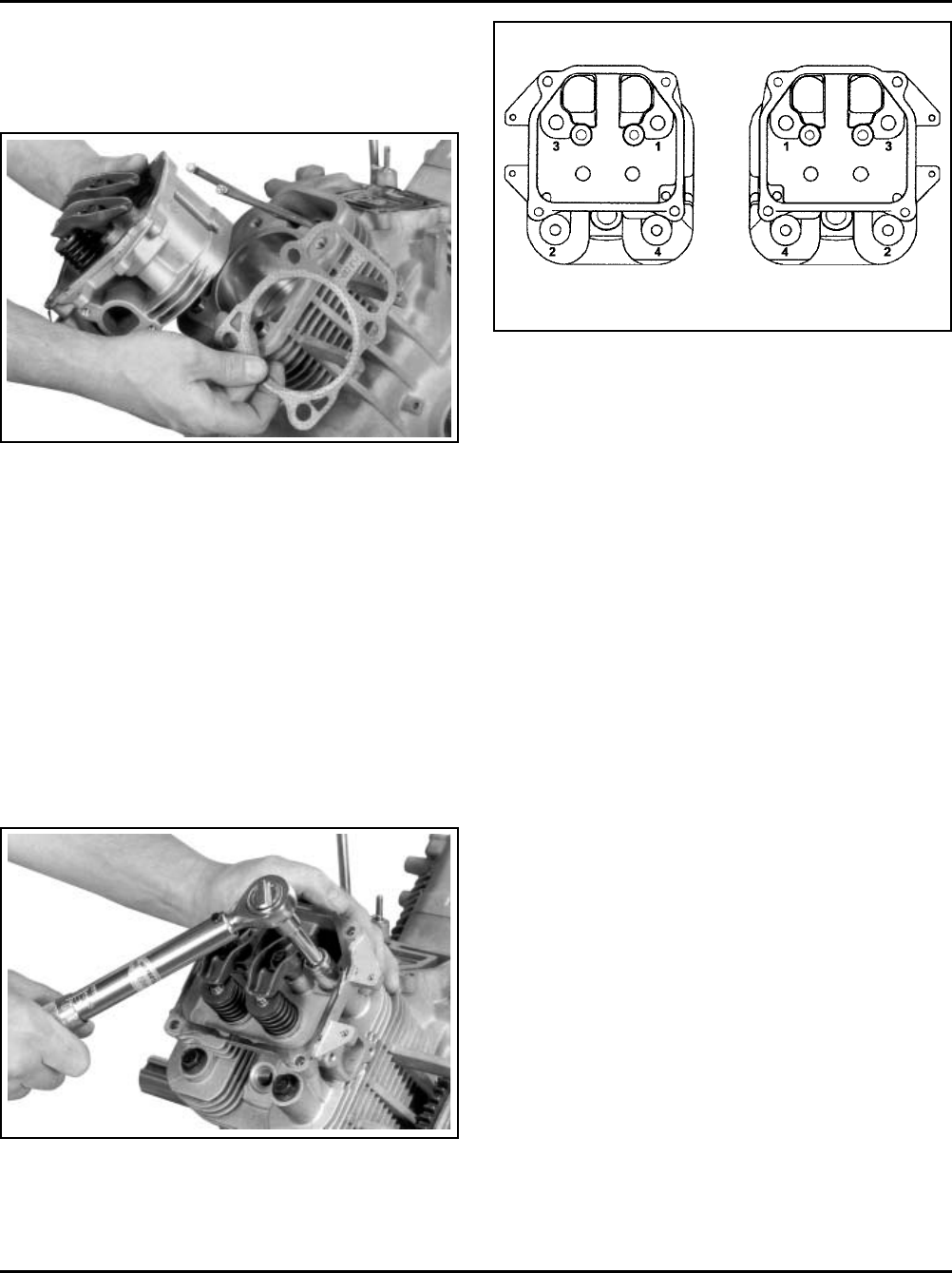
4. Torque the hex. flange screws in two stages; first
to 22.6 N·m (200 in. lb.), then finally to 41.8 N·m
(370 in. lb.), following the sequence in Figure
11-42.
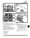
Heads secured with hex. flange screws:
2. Install a new cylinder head gasket, (with printing
up).
#1
#2