


5B.24
Section 5B
EFI Fuel System
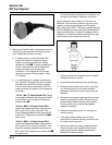
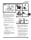
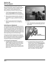
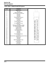
Figure 5B-37. Throttle Linkage/Governor Lever
Connection.
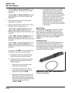
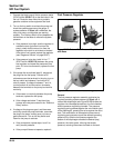
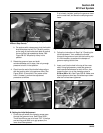
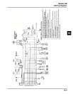
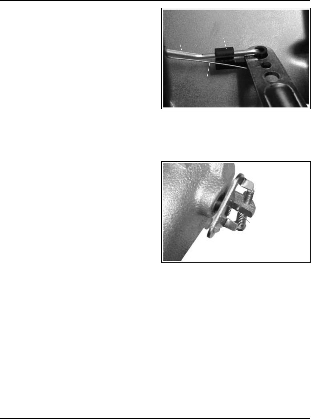
2. Check if the engine has a high-speed throttle stop
screw installed in the manifold casting boss. See
Figure 5B-38.
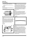
The idle speed adjustment procedure remains the
same for engines with or without a dampening spring.
Typically, no periodic servicing is necessary in this
area. If however, removal/replacement of the
dampening spring is required, reinstall it as follows:
1. Thread the spring onto the end of idle screw
leaving 1-3 mm (0.039-0.117 in.) of the spring
extending beyond the end of the idle speed screw.
2. Secure spring onto the screw with a small amount
of Permabond
™
LM-737 or equivalent Loctite
®
adhesive. Do not get any adhesive on free coils of
spring.
3. Start the engine and recheck the idle speed
settings, after sufficient warm up. Readjust as
required.
Initial Governor Adjustment
The initial governor adjustment is especially critical on
EFI engines because of the accuracy and sensitivity of
the electronic control system. Incorrect adjustment can
result in overspeed, loss of power, lack of response, or
inadequate load compensation. If you encounter any of
these symptoms and suspect them to be related to the
governor setting, the following should be used to check
and/or adjust the governor and throttle linkage.
If the governor/throttle components are all intact, but
you think there may be a problem with the adjustment,
follow Procedure A to check the setting. If the governor
lever was loosened or removed, go immediately to
Procedure B to perform the initial adjustment.
A. Checking the Initial Adjustment
1. Unsnap the plastic linkage bushing attaching the
throttle linkage to the governor lever. See Figure
5B-37. Unhook the damper spring from the lever,
separate the linkage from the bushing, and
remove the bushing from the lever. Mark the hole
position and unhook the governor spring from the
governor lever.
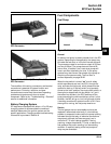
Linkage
Bushing
Throttle
Linkage
Damper
Spring
High-Speed
Throttle Stop Screw
Figure 5B-38. Throttle Details.
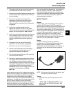
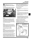
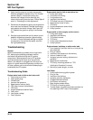
a. On engines without a stop screw, pivot the
throttle shaft and plate assembly into the “Full
Throttle” position. Insert a 1.52 mm (0.060 in.)
feeler gauge between the rear tang of the
throttle shaft plate and the underside of the
manifold boss. Use a locking pliers (needle
nose works best) to temporarily clamp the
parts in this position. See Figure 5B-39.