


11.14
Section 11
Reassembly
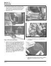
5. Repeat the above steps for the remaining
cylinder. Do not interchange parts from the
cylinder heads.
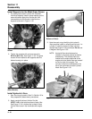
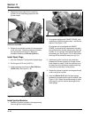
Figure 11-47. Using Spanner Wrench to Lift Rocker
Arm Over Push Rod.
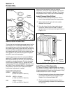
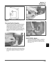
6. Rotate the crankshaft to check for free operation
of the valve train. Check the clearance between
the valve spring coils at full lift. Minimum
allowable clearance is 0.25 mm (0.010 in.).
Install Spark Plugs
1. Use new Champion
®
(or equivalent) spark plugs.
2. Set the gap at 0.76 mm (0.030 in.).
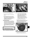
3. Install new plugs and torque to 24.4-29.8 N·m
(18-22 ft. lb.). See Figure 11-48.
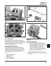
Figure 11-48. Installing Spark Plugs.
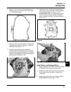
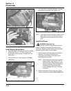
Install Ignition Modules
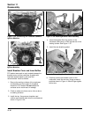
1. Rotate the flywheel to position the magnet away
from the ignition module bosses.
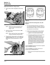
Figure 11-49. Installing Ignition Module.
2. On engines equipped with SMART-SPARK
™
both
modules are installed the same way - with the two
tabs out. See Figure 11-55.
On engines are not equipped with SMART-
SPARK
™
the modules are installed with the spark
plug lead wire from module always away from the
cylinder. On #1 cylinder, the single kill tab should
be towards you. See Figure 11-54. On #2 cylinder,
the single kill tab should be away from you (in).
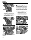
3. Install each ignition module to the crankcase
bosses with the two screws (hex. flange or allen
head, based on model). Slide the modules up as
far away from the flywheel as possible and snug
the screws to hold them in that position.
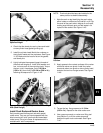
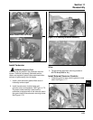
4. Rotate the flywheel to position the magnet directly
under one ignition module.
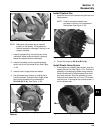
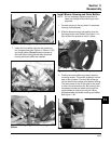
5. Insert a 0.30 mm (0.012 in.) flat feeler gauge
between the magnet and the ignition module. See
Figure 11-50. Loosen the screws enough to allow
the magnet to pull the module down against the
feeler gauge.