


9.10
Section 9
Disassembly
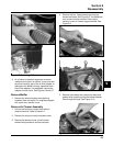
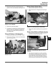
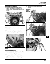
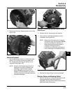
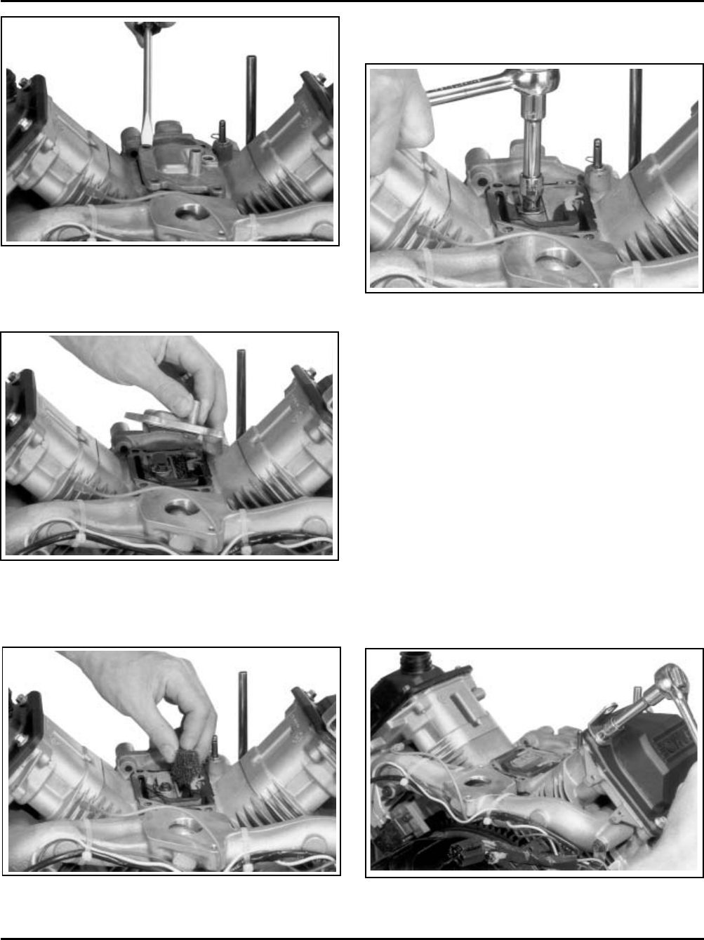
7. Remove the hex. flange screw, breather reed
retainer and breather reed. See Figure 9-39.
Figure 9-39. Removing Breather Reed.
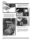
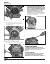
Remove Valve Covers
Three valve cover designs have been used. The
earliest type used a gasket and RTV sealant between
the cover and sealing surface of the cylinder head. The
second type had a black O-Ring installed in a groove
on the underside of the cover and may have metal
spacers in the bolt holes. The latest design uses a
brown O-Ring, and the bolt holes spacers are molded
in place.
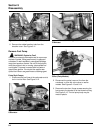
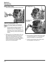
1. Remove the four hex. flange screws securing
each valve cover. Note the position of any
attached brackets or lifting straps.
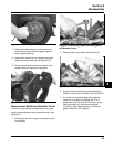
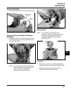
2. Remove the valve covers, valve cover gaskets or
O-Rings and any brackets or lifting straps. Note
which side of the engine has the oil fill and or fuel
pump valve cover. See Figure 9-40.
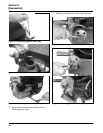
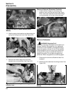
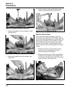
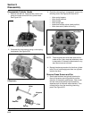
Figure 9-36. Breaking Breather Cover Seal.
5. Remove the breather cover and gasket (if used).
See Figure 9-37.
Figure 9-37. Removing Breather Cover.
6. Remove the breather filter from chamber. See
Figure 9-38.
Figure 9-40. Removing Valve Covers.
Figure 9-38. Removing Breather Filter.