


8.10
Section 8
Electrical System and Components
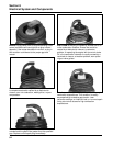
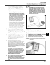
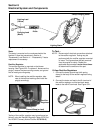
5. Check and/or adjust the ignition module air
gap(s). An air gap of 0.28/0.33 mm
(0.011/0.013 in.) must be maintained under all
three legs of the ignition module(s). Checking/
adjusting should be performed with the parts
at room temperature.
a. If the module was not loosened or
replaced, check that the specified air gap is
present under all three legs. If the gap is
correct, reinstall the second mounting
screw removed earlier and recheck gap
after tightening.
b. If the gap is incorrect, or the module was
loosened or replaced, adjust the gap as
follows.
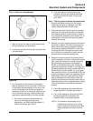
1) Turn the flywheel magnet away from the
module position.
2) Attach the module to the mounting legs,
pull it away from the flywheel, and snug
the screws to hold it temporarily.
3) Rotate the flywheel so the magnet is
centered under the module.
4) Position a 0.33 mm (0.013 in.) feeler
gauge between the magnet and all three
legs of the module. The ignition module
air gap is critical to proper system
performance. Do not attempt to set it
with a business card or folded
microfiche card, use the feeler gauge
specified. A 0.33 mm (0.013 in.) feeler
gauge is recommended because the
gap has a tendency to close slightly as
the module mounting screws are
tightened.
5) Loosen the mounting screws, allow the
magnet to pull the module down against
the feeler gauge, and retighten the
mounting screws.
6) Rotate the flywheel to remove the feeler
gauge, position the magnet back under
the module, and recheck that the
specified gap, minimum of 0.28 mm
(0.011 in.) exists under each leg of the
module. When you are certain the gap is
correct, torque the module mounting
screws to 4.0 N·m (35 in. lb.). On a
twin cylinder engine, repeat these 6
steps to set the opposite side ignition
module.
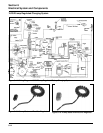
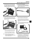
6. Reattach the lead wires to the ignition
module(s), noting if resistance is felt, indicating
a snug fit between the male and female
terminals. If any connections do not feel snug,
disconnect the lead, lightly pinch the female
terminal with a pliers, and recheck the fit.
7. When the integrity of all connections has been
verified, repeat the spark test (Test 2).
a. If a strong, steady spark is now present
(both sides on a twin), your problem should
be corrected. Go to step 4 of Test 5.
b. If there is still a spark problem, perform all
of Test 5.
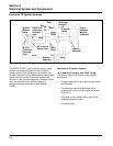
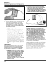
Test 5 – Test the SAM
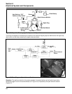
1. Trace the red power source lead from the SAM
to the harness connection. Separate the
connector and connect the red lead of a DC
voltmeter to the harness terminal. Trace the
ground lead from the SAM (black on singles,
green on twins) to the grounding screw.
Connect the black voltmeter lead to the eyelet
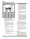
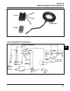
2
1
4
2
1
3
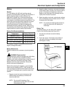
24 584 03 or
24 584 11
(1 11/16 in. H)
24 584 15-S or
24 584 36-S
(2 1/16 in. H)
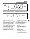
tseT
latigiDesU(
)retemmhO
3048542
1148542
)H.ni61/111(
S-5148542
)H.ni61/12(
S-6348542
)H.ni61/12(
.oNmorF
4ot1
ot549
smho5711
ot098
smho5711
ot095
smho616
.oNmorF
4ot2
ot941
smho661
ot911
smho631
ot381
smho802
.oNmorF
4ot3
ot0573
smho0007
ot0065
smho0009
ot0008
smho000,04
Ignition Module Resistance Table