11.13
Section 11
Reassembly
11
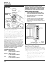
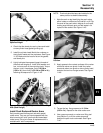
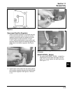
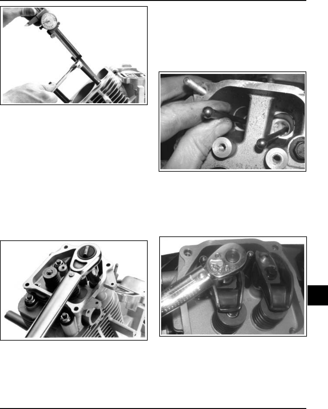
Figure 11-43. Installing New Mounting Studs to
Specified Height.
4. Check that the dowel pins are in place and install
a new cylinder head gasket (printing up).
5. Install the cylinder head. Match the numbers on
the cylinder heads and the crankcase. See Figure
11-36. Make sure the head is flat on the gasket
and dowel pins.
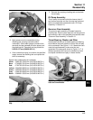
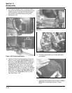
6. Lightly lubricate the exposed (upper) threads of
the studs with engine oil. Install a flat washer and
hex. nut onto each of the mounting studs. Torque
the hex. nuts in two stages; first to 16.9 N·m
(150 in. lb.), then finally to 33.9 N·m (300 in. lb.),
following the sequence in Figure 11-42.
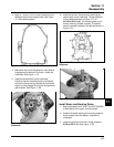
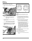
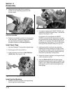
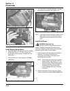
Figure 11-46. Torquing Rocker Arm Screws.
3. Torque the hex. flange screws to 11.3 N·m
(100 in. lb.). Repeat for the other rocker arm.
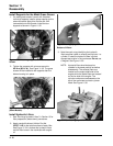
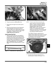
4. Use a spanner wrench or rocker arm lifting tool
(see Section 2), to lift the rocker arms and
position the push rods underneath. See Figure
11-47.
NOTE: Push rods should always be installed in the
same position as before disassembly.
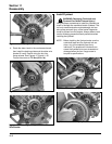
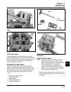
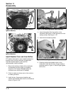
1. Note the mark or tag identifying the push rod as
either intake or exhaust and cylinder #1 or #2. Dip
the ends of the push rods in engine oil and install,
making sure that each push rod ball seats in its
hydraulic lifter socket. See Figure 11-45.
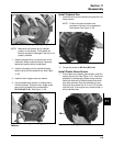
Figure 11-44. Torquing the Cylinder Head Mounting
Nuts (Stud Design).
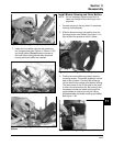
Install Push Rods and Rocker Arms
Early models used hollow push rods with special
rocker arms. They are not interchangeable with the
later/current style “solid” push rods and associated
rocker arms. Do not mix these. A replacement kit is
available with “solid” components.
Figure 11-45. Install Push Rods in Their Original
Position.
2. Apply grease to the contact surfaces of the rocker
arms and rocker arm pivots. Install the rocker
arms and rocker arm pivots on one cylinder head,
and start the two hex. flange screws. See Figure
11-46.


