8.4
Section 8
Electrical System and Components
The SMART-SPARK
™
ignition system used on some
models is an advanced version of the CD ignition
system used on other CH engines. Its operation can
be best understood by first understanding the standard
system and how it works. Since both systems will
continue in use, it is advantageous to understand them
both. The operation of the standard system is
explained first then expanded to cover SMART-
SPARK
™
.
Electronic CD Ignition Systems
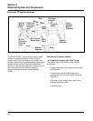
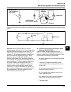
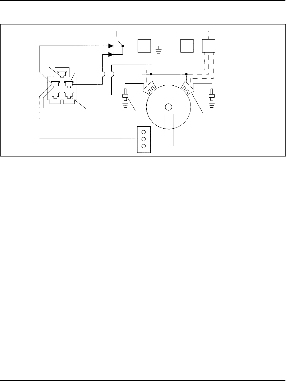
Figure 8-3. Electronic CD Ignition System (For Customer Connected Tractor Applications).
Operation of CD Ignition Systems
A. Capacitive Discharge with Fixed Timing
This system (Figure 8-3) consists of the following
components:
• A magnet assembly which is permanently affixed
to the flywheel.
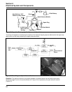
• Two electronic capacitive-discharge ignition
modules which mount on the engine crankcase
(Figure 8-4).
• A kill switch (or key switch) which grounds the
modules to stop the engine.
• Two spark plugs.
Oil Pressure
Safety Input
Rectifier-
Regulator
B+ and
Carburetor
Solenoid
Input
Ignition
Module
Input
Carburetor
Solenoid
Oil
Pressure
Safety
Red
Green
White
Ignition
Modules
Spark
Plugs
B+
Violet
Red
Starter and
Carburetor
Solenoid
Input
White
Red
Red
Spark
Advance
Module
(Optional)


