


5B.15
Section 5B
EFI Fuel System
5B
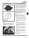
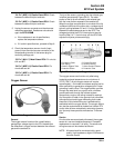
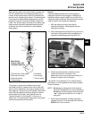
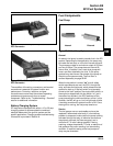
When the key switch is on and the relay is closed, the
fuel rail is pressurized, and voltage is present at the
injector. At the proper instant, the ECU completes the
ground circuit, energizing the injector. The valve needle
in the injector is opened electromagnetically, and the
pressure in the fuel rail forces fuel down through the
inside. The “director plate” at the tip of the injector (see
inset) contains a series of calibrated openings which
directs the fuel into the manifold in a cone-shaped
spray pattern.
Service
Injector problems typically fall into three general
categories: electrical, dirty/clogged, or leakage. An
electrical problem usually causes one or both of the
injectors to stop functioning. Several methods may be
used to check if the injectors are operating.
1. With the engine running at idle, feel for
operational vibration, indicating that they are
opening and closing.
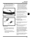
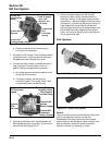
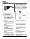
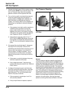
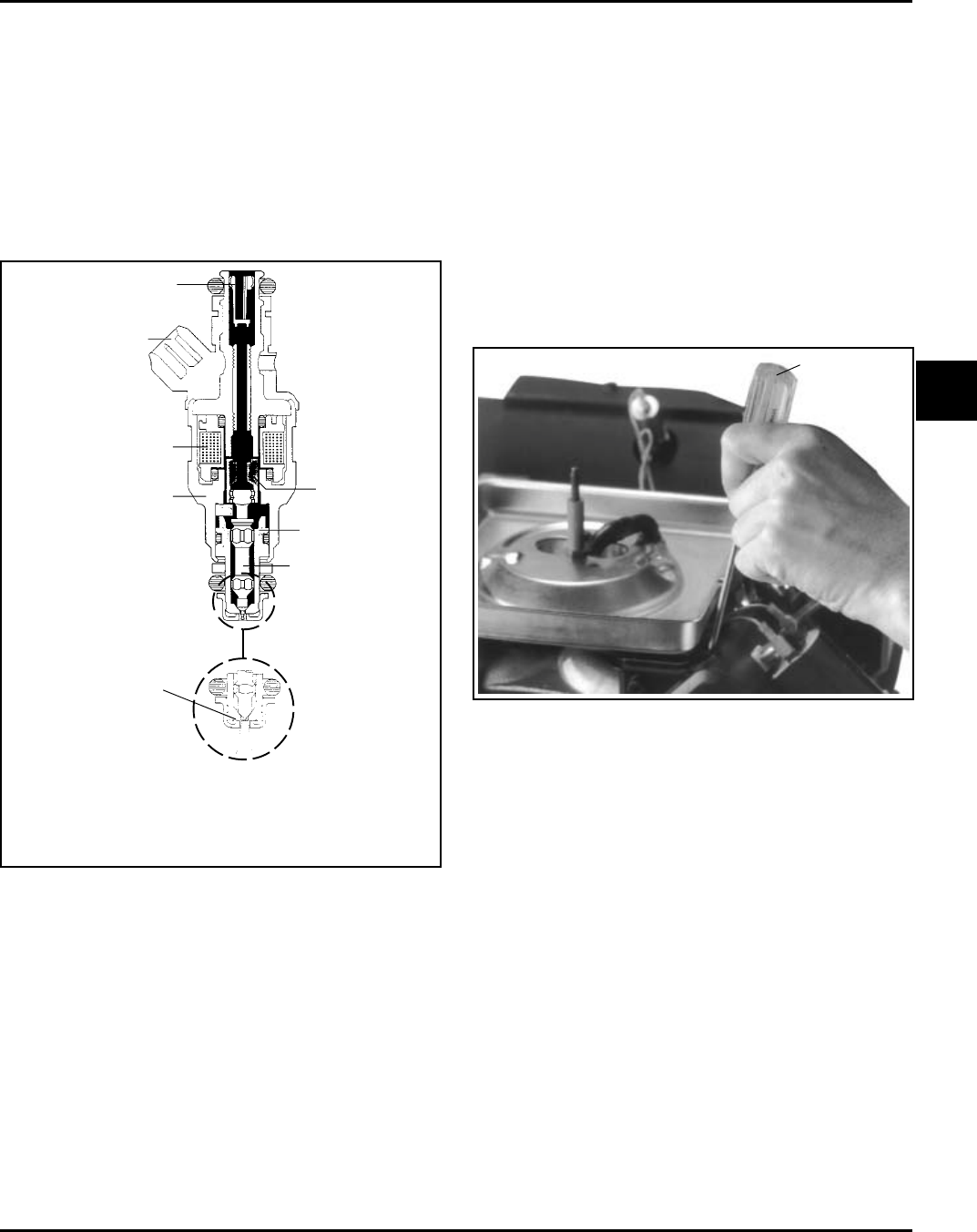
2. When temperatures prohibit touching, listen for a
buzzing or clicking sound with a screwdriver or
mechanic’s stethoscope (see Figure 5B-19).
Figure 5B-18. Fuel Injector Details.
The injector is opened and closed once for each
crankshaft revolution, however only one-half the total
amount of fuel needed for one firing is injected during
each opening. The amount of fuel injected is controlled
by the ECU and determined by the length of time the
valve needle is held open, also referred to as the
“injection duration” or “pulse width”. It may vary in
length from 1.5-8 milliseconds depending on the speed
and load requirements of the engine.
Figure 5B-19. Checking Injectors.
3. Disconnect the electrical connector from an
injector and listen for a change in idle
performance (only running on one cylinder) or a
change in injector noise or vibration.
If an injector is not operating, it can indicate either a
bad injector, or a wiring/electrical connection problem.
Check as follows:
NOTE: Do not apply voltage to the fuel injector(s).
Excessive voltage will burn out the injector(s).
Do not ground the injector(s) with the ignition
“on”. Injector(s) will open/turn on if relay is
energized.
1. Disconnect the electrical connector from both
injectors. Plug the 12 volt test light (SPX Part No.
KO3217-6) in one connector.
1. Filter strainer in fuel supply
2. Electrical connection
3. Solenoid winding
4. Valve housing
Multi-Orifice
Director Plate with
Calibrated Opening
5. Armature
6. Valve body
7. Valve needle
Listen Here
1
2
3
4
5
6
7