


5B.18
Section 5B
EFI Fuel System
4. If the secondary resistance is not within
the specified range, unscrew the spark
plug lead nut from the coil secondary
tower and remove the plug lead. Repeat
step b. 3, testing from the secondarytower
terminal to the red primary terminal. If
resistance is now correct, the coil is good,
but the spark plug lead is faulty, replace
the lead. If step b. 2 resistance was
incorrect and/or the secondary resistance
is still incorrect, the coil is faulty and needs
to be replaced.
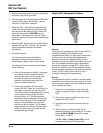
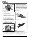
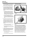
Spark Plugs
EFI engines are equipped with Champion
®
RC12YC
(Kohler Part No. 12 132 02-S) resistor style spark
plugs. Equivalent alternate brand plugs can also be
used, but must be a resistor style plug or permanent
damage to the ECU will occur in addition to affecting
operation. Proper spark plug gap is 0.76 mm
(0.030 in.).
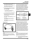
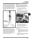
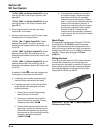
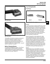
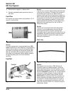
Wiring Harness
The wiring harness used in the EFI system connects
the electrical components, providing current and
ground paths for the system to operate. All input and
output signaling occurs through a special all weather
connector that attaches and locks to the ECU (see
Figures 5B-23, 5B-24, and 5B-25).
“24 Pin” (MSE 1.0) Plastic-Cased ECU: Locate
pins #22 and #23 in the 24 pin connector. See
page 5B.31.
“32 Pin” (MSE 1.1) Plastic Cased ECU: Locate
pins #30 and #31 in the 32 pin connector. See
page 5B.32.
2. Disconnect connector from relay and locate
terminal #87 in connector.
3. Using an ohmmeter set on the Rx1 scale, check
the resistance in circuits as follows:
“35 Pin” (MA 1.7) Metal-Cased ECU: Check
between terminal #87 and pin #1 for coil #1.
Repeat the test between terminal #87 and pin #19
for coil #2.
“24 Pin” (MSE 1.0) Plastic-Cased ECU: Check
between terminal #87 and pin #22 for coil #1.
Repeat the test between terminal #87 and pin #23
for coil #2.
“32 Pin” (MSE 1.1) Plastic-Cased ECU: Check
between terminal #87 and pin #30 for coil #1.
Repeat the test between terminal #87 and pin #31
for coil #2.
A reading of 1.8-4.0
ΩΩ
ΩΩ
Ω in each test indicates that
the wiring and coil primary circuits are OK.
a. If reading(s) are not within specified range,
check and clean connections and retest.
b. If reading(s) are still not within the specified
range, test the coils separately from main
harness as follows:
1. Disconnect the red and black primary
leads from the coil terminals.
2. Connect an ohmmeter set on the Rx1
scale to the primary terminals. Primary
resistance should be 1.8-2.5
ΩΩ
ΩΩ
Ω.
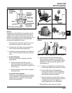
3. Disconnect the secondary lead from the
spark plug. Connect an ohmmeter set on
the Rx10K scale between the spark plug
boot terminal and the red primary terminal.
Secondary resistance should be
13,000-17,500
ΩΩ
ΩΩ
Ω.
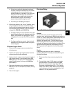
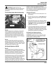
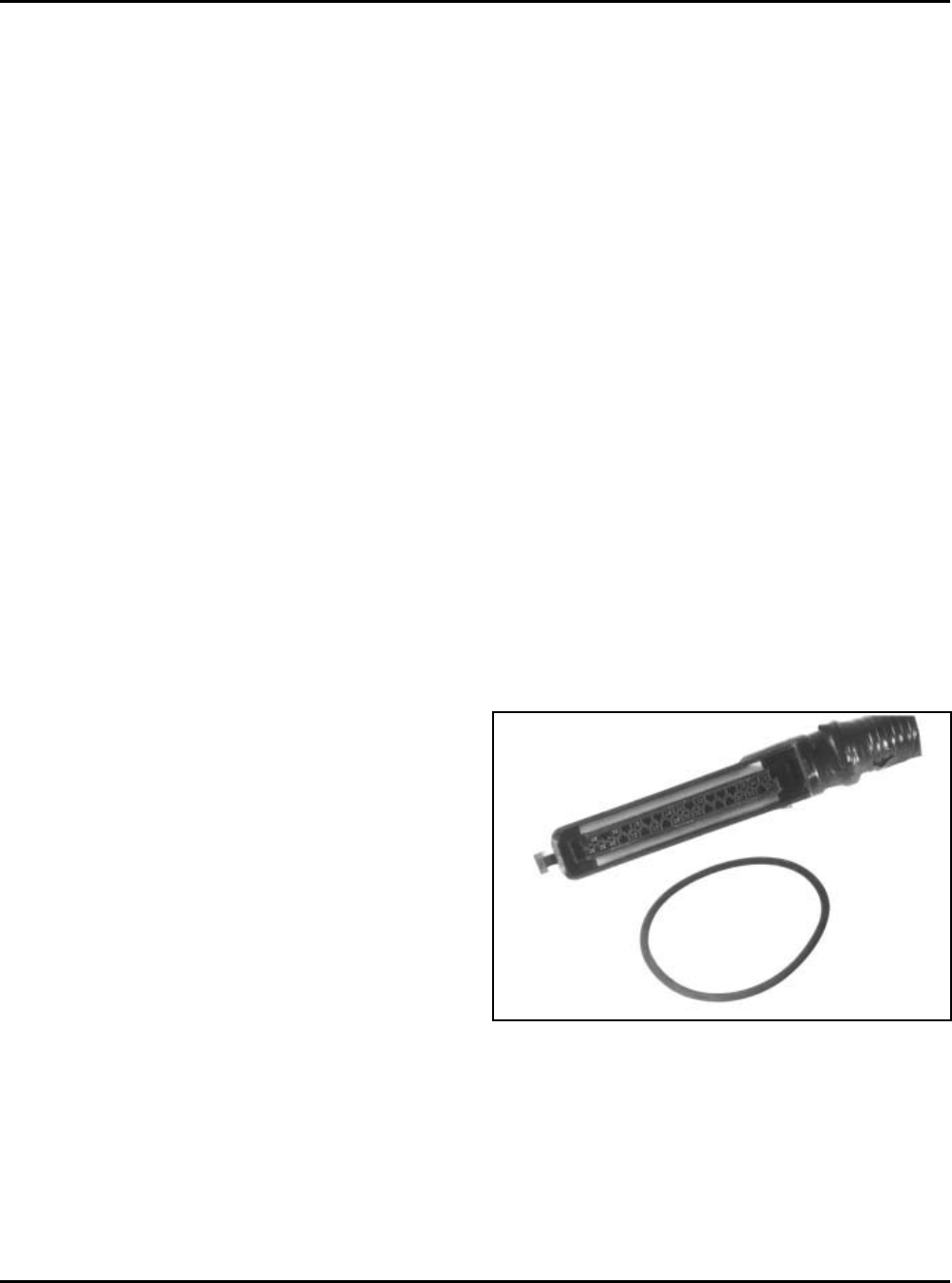
Figure 5B-23. “35 Pin” (MA 1.7) Metal-Cased ECU
Connector and O-Ring.