


8.17
Section 8
Electrical System and Components
8
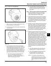
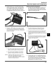
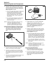
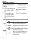
3. Plug the tester into a 110 volt AC outlet supply
and turn on the power switch. See Figure 8-22.
The ‘‘POWER’’ light should be illuminated and
one of the four status lights may be on as well.
This does not represent the condition of the part.
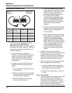
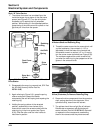
Figure 8-23.
a. If the “OK” (green) light comes on and stays
steady, the part is good and may be used.
b. If any other light is displayed,* the rectifier-
regulator is faulty and should not be used.
*NOTE: A flashing “LOW” light can also occur as a
result of an inadequate ground lead
connection. Make certain connection location
is clean and clamp is secure.
Figure 8-22.
4. Press the ‘‘TEST’’ button until a “click” is heard
and then release. See Figure 8-23. Momentarily
one of the four lights will illuminate, indicating the
condition of the part.
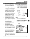
20/25 Amp Rectifier-Regulators
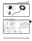
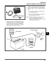
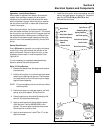
1. Connect the single lead adapter in between the
B+ (center) terminal of rectifier-regulator being
tested and the squared single end of the tandem
adapter lead. See Figure 8-24.
Figure 8-24.
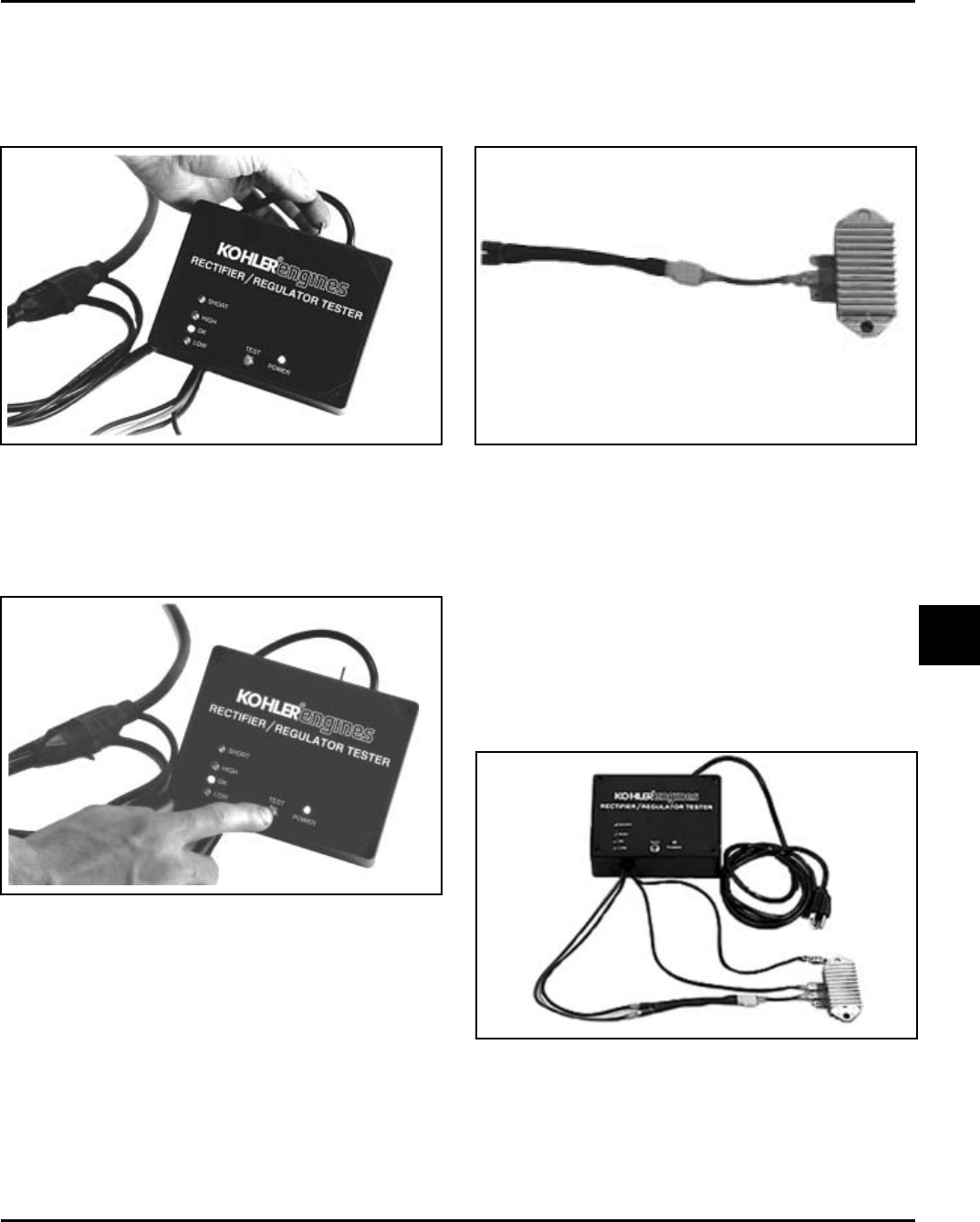
2. Connect the tester ground lead (with spring
clamp) to the body of the rectifier-regulator.
3. Connect the red lead and one of the black leads
to the pair of terminals on the open end of the
tandem adapter lead (connections are not location
specific).
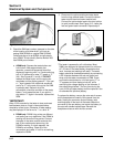
4. Connect the remaining black lead from the tester
to one of the outer AC terminals on the rectifier-
regulator. See Figure 8-25.
Figure 8-25.
5. Plug the tester into a 110 volt AC outlet and turn
on the power switch. The ‘‘POWER’’ light should
be illuminated and one of the four status lights
may be on as well. See Figure 8-22. This does
not represent the condition of the part.