


11.7
Section 11
Reassembly
11
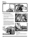
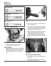
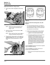
Figure 11-19. Closure Plate Sealant Pattern.
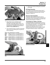
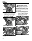
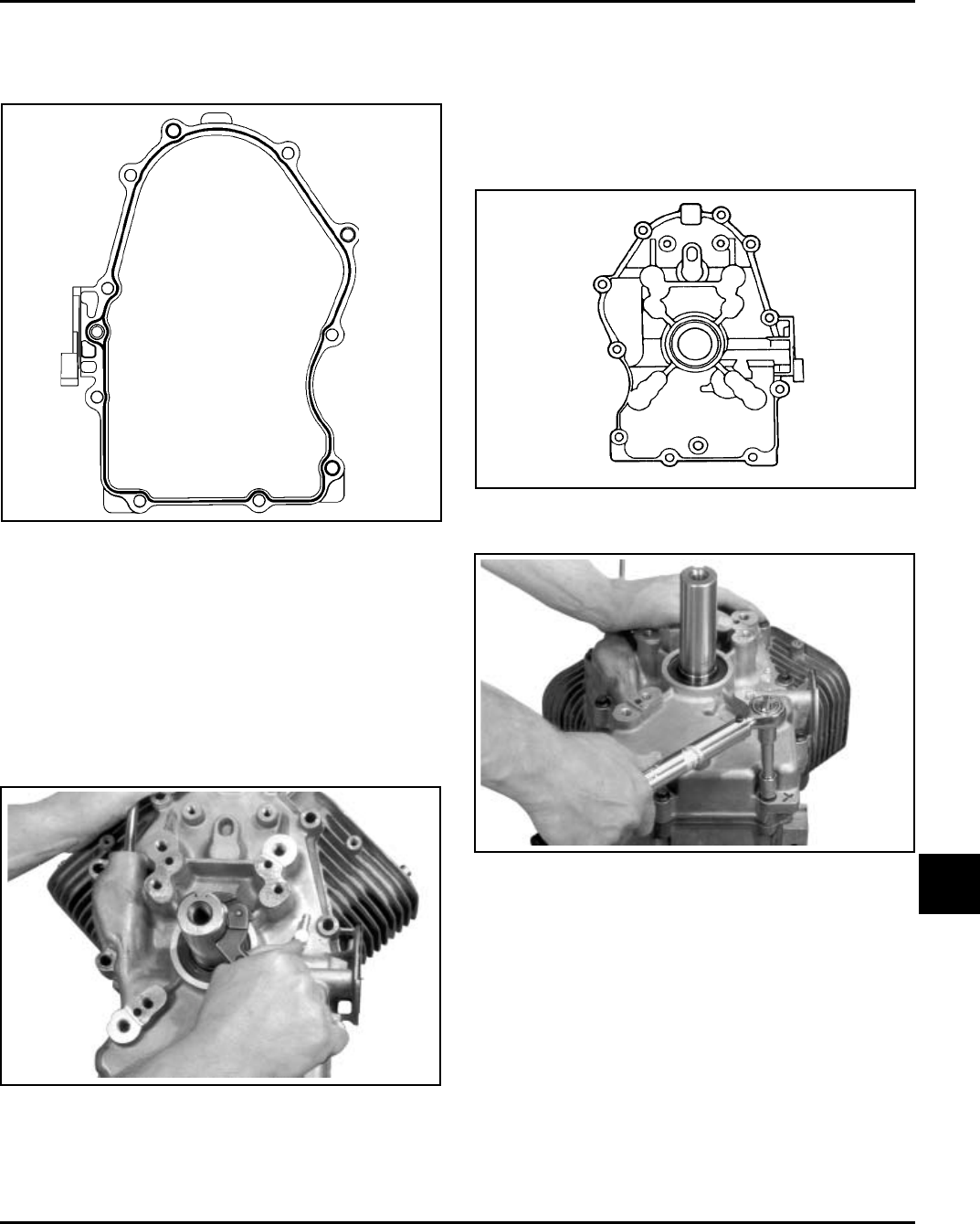
4. Make sure the end of the governor cross shaft is
lying against the bottom of cylinder 1 inside the
crankcase. See Figure 11-13.
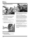
5. Install the closure plate to the crankcase.
Carefully seat the camshaft and the crankshaft
into their mating bearings. Rotate the crankshaft
slightly to help engage the oil pump and governor
gear meshes. See Figure 11-20.
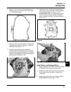
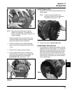
Figure 11-22. Torquing Closure Plate Fasteners.
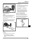
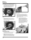
Install Stator and Backing Plates
1. Apply pipe sealant with Teflon
®
(Loctite
®
No 59241
or equivalent) to the stator mounting holes.
2. Position the stator aligning the mounting holes so
that the leads are at the bottom, towards the
crankcase.
3. Install and torque the two hex. flange screws to
6.2 N·m (55 in. lb.). See Figure 11-23.
3. Apply a 1.5 mm (1/16 in.) bead of sealant to the
sealing surface of the closure plate. See Figure
11-19 for sealant pattern.
Figure 11-20. Using Spanner Wrench to Turn
Crankshaft.
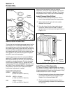
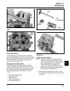
1
10
8
6
4
2
9
7
5
3
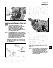
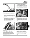
6. Install the ten hex. flange screws securing the
closure plate to the crankcase. Torque fasteners
in the sequence shown in Figure 11-21 to
24.4 N·m (216 in. lb.). On some engines one of
the ten mounting screws is plated. The plated
screw is typically installed in the #6 hole shown in
Figure 11-21.
Figure 11-21. Closure Plate Fastener Torque
Sequence.