When all the liners are released, tip the
cylinder block/crankcase on its side and
remove each liner from the top of the block.
As each liner is removed, stick masking tape
on its left-hand (transmission side) face, and
write the cylinder number on the tape. No 1
cylinder is at the transmission (flywheel/
driveplate) end of the engine. Remove the
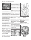
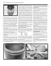
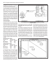
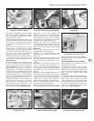
paper base seal or O-ring from the base of
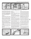
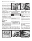
each liner, and discard (see illustration).
12 Check each cylinder liner for scuffing and
scoring. Check for signs of a wear ridge at the
top of the liner, indicating that the bore is
excessively worn.
13 If the necessary measuring equipment is
available, measure the bore diameter of each
cylinder liner at the top (just under the wear
ridge), centre, and bottom of the cylinder
bore, parallel to the crankshaft axis.
14 Next, measure the bore diameter at the
same three locations, at right-angles to the
crankshaft axis.
15 Repeat the procedure for the remaining
cylinder liners.
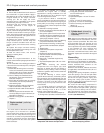
16 If the liner wear is excessive at any point,
or if the cylinder liner walls are badly scored or
scuffed, then renewal of the relevant liner
assembly will be necessary. If there is any
doubt about the condition of the cylinder
bores, seek the advice of a Peugeot dealer or
engine reconditioning specialist.
17 If renewal is necessary, new liners,
complete with pistons and piston rings, can
be purchased from a Peugeot dealer. Note
that it is not possible to buy liners individually
- they are supplied only as a matched
assembly complete with piston and rings.
18 To allow for manufacturing tolerances,
pistons and liners are separated into three
size groups. The size group of each piston is
indicated by a letter (A, B or C) stamped onto
its crown, and the size group of each liner is
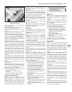
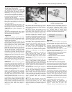
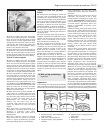
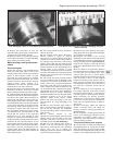
indicated by a series of 1 to 3 notches on the
upper lip of the liner (see illustration); a single
notch for group A, two notches for group B,
and three notches for group C (on some
engines the actual letters A, B, C may also
appear on the liners instead of the notches).
Ensure that each piston and its respective
liner are both of the same size group. It is
permissible to have different size group piston
and liner assemblies fitted to the same
engine, but never fit a piston of one size group
to a liner in a different group.
19 Prior to installing the liners it is necessary
to check the liner protrusion above the top of
the cylinder block as follows.
XV, XW and XY series engines with
paper type base seals
20 If the cylinder liners had paper type base
seals, the liner protrusion must be measured
and seals of the correct thickness selected.
21 Paper base seals are available in four
different thicknesses:
Blue 0.087 mm
White 0.102 mm
Red 1.122 mm
Yellow 0.147 mm
22 The correct protrusion for each liner
above the surface of the cylinder block is
given in the Specifications and it is preferable
to aim for the greater protrusion when
selecting new seals.
23 Fit the liners without the seals into their
original locations. If new liners are being fitted,
they of course can be fitted in any order.
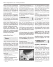
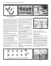
24 Using a dial indicator or feeler blades and
a straight-edge, measure the protrusion of
each liner above the top of the cylinder block
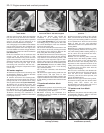
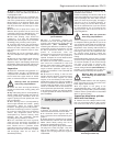
(see illustration).
25 It is now a simple matter to select a paper
base seal which, when its thickness is added
to the recorded protrusion will equal the
specified protrusion.
26 Make sure that the difference in
protrusion between adjacent liners does not
exceed 0.04 mm. If it does, reduce the seal
thickness on the greater protruding liner.
27 If new liners are being fitted, the
protrusion differences can be eliminated by
changing the position of the liner in the block
or by twisting it on its base.
28 Prior to installing the liners, thoroughly
clean the liner mating surfaces in the cylinder
block, and use fine abrasive paper to polish
away any burrs or sharp edges which might
damage the liner base seals. Clean the liners
and wipe dry, then fit the selected paper seals
to the base of each liner so that their tabs are
diametrically opposite to the liner rim marks.
To aid installation, apply a smear of oil to the
base of the liner.
29 Insert each liner into its correct location in
the block then, using a hammer and a block of
wood, tap each liner lightly but fully onto its
locating shoulder. Wipe clean, then lightly oil,
all exposed liner surfaces, to prevent rusting.
XV, XW and XY series engines with
O-ring type seals
30 If the original liners are being refitted then
the projection should be correct once new
O-ring seals have been fitted.
31 If new liners are being fitted, then
measure the protrusion of each liner without
its seal as described in paragraph 24 and
compare the figures obtained with those given
in the Specifications.
32 If the difference between adjacent liners
exceeds 0.05 mm, rotate the liners through
half a turn or interchange the liner position in
the block.
2D•14 Engine removal and overhaul procedures
9.11 Cylinder liner with paper base seal
9.18 Cylinder liner size group marking 9.24 Measuring cylinder liner protrusion


