3 If the alternator output is suspect even
though the warning light functions correctly,
the regulated voltage may be checked as
follows.
4 Connect a voltmeter across the battery
terminals and start the engine.
5 Increase the engine speed until the
voltmeter reading remains steady; the reading
should be approximately 12 to 13 volts, and
no more than 14 volts.
6 Switch on as many electrical accessories
(eg, the headlights, heated rear window and
heater blower) as possible, and check that the
alternator maintains the regulated voltage at
around 13 to 14 volts.
7 If the regulated voltage is not as stated, the
fault may be due to worn brushes, weak brush
springs, a faulty voltage regulator, a faulty
diode, a severed phase winding or worn or
damaged slip rings. The alternator should be
renewed or taken to an auto-electrician for
testing and repair.
6 Alternator - removal and
refitting
2
Removal
1 Disconnect the battery negative lead.
2 Remove the auxiliary drivebelt as described
in Chapter 1.
3 Where necessary, refer to Chapter 4 and
move the relevant air cleaner components to
one side for increased access.
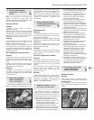
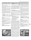
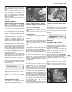
4 Disconnect the wiring from the alternator
(see illustration).
5 Unscrew the pivot and adjustment bolts
and lift the alternator from the engine. On
certain models note that the alternator front
bracket is slotted to allow the pivot bolt to
remain in the bracket on the engine.
Refitting
6 Refitting is a reversal of removal, but tension
the drivebelt, as described in Chapter 1.
7 Alternator - testing and
overhaul
5
If the alternator is thought to be suspect, it
should be removed from the vehicle and taken
to an auto-electrician for testing. Most auto-
electricians will be able to supply and fit
brushes at a reasonable cost. However, check
on the cost of repairs before proceeding as it
may prove more economical to obtain a new
or exchange alternator.
8 Starting system - testing
1
Note: Refer to the precautions given in
“Safety first!” and in Section 1 of this Chapter
before starting work.
1 If the starter motor fails to operate when the
ignition key is turned to the appropriate
position, the following possible causes may
be to blame.
a) The battery is faulty.
b) The electrical connections between the
switch, solenoid, battery and starter
motor are somewhere failing to pass the
necessary current from the battery
through the starter to earth.
c) The solenoid is faulty.
d) The starter motor is mechanically or
electrically defective.
2 To check the battery, switch on the
headlights. If they dim after a few seconds,
this indicates that the battery is discharged -
recharge (see Section 3) or renew the battery.
If the headlights glow brightly, operate the
ignition switch and observe the lights. If they
dim, then this indicates that current is
reaching the starter motor, therefore the fault
must lie in the starter motor. If the lights
continue to glow brightly (and no clicking
sound can be heard from the starter motor
solenoid), this indicates that there is a fault in
the circuit or solenoid - see following
paragraphs. If the starter motor turns slowly
when operated, but the battery is in good
condition, then this indicates that either the
starter motor is faulty, or there is considerable
resistance somewhere in the circuit.
3 If a fault in the circuit is suspected,
disconnect the battery leads (including the
earth connection to the body), the
starter/solenoid wiring and the
engine/transmission earth strap. Thoroughly
clean the connections, and reconnect the
leads and wiring, then use a voltmeter or test
lamp to check that full battery voltage is
available at the battery positive lead
connection to the solenoid, and that the earth
is sound. Smear petroleum jelly around the
battery terminals to prevent corrosion -
corroded connections are amongst the most
frequent causes of electrical system faults.
4 If the battery and all connections are in
good condition, check the circuit by
disconnecting the wire from the solenoid
blade terminal. Connect a voltmeter or test
lamp between the wire end and a good earth
(such as the battery negative terminal), and
check that the wire is live when the ignition
switch is turned to the “start” position. If it is,
then the circuit is sound - if not the circuit
wiring can be checked as described in
Chapter 12.
5 The solenoid contacts can be checked by
connecting a voltmeter or test lamp between
the battery positive feed connection on the
starter side of the solenoid, and earth. When
the ignition switch is turned to the “start”
position, there should be a reading or lighted
bulb, as applicable. If there is no reading or
lighted bulb, the solenoid is faulty and should
be renewed.
6 If the circuit and solenoid are proved
sound, the fault must lie in the starter motor.
In this event, it may be possible to have the
starter motor overhauled by a specialist, but
check on the cost of spares before
proceeding, as it may prove more economical
to obtain a new or exchange motor.
9 Starter motor - removal and
refitting
2
Removal
1 Disconnect the battery negative lead.
2 Where necessary, refer to Chapter 4 and
move the relevant air cleaner components to
one side for increased access.
3 On GTI models, remove the inlet manifold,
with reference to the relevant Part of Chap-
ter 4.
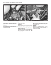
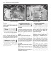
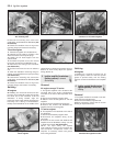
4 Disconnect the wiring from the solenoid
(see illustration).
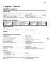
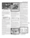
5 Unscrew the bolts securing the brush end
bracket to the engine (see illustration).
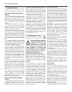
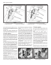
6 Unscrew the mounting bolts at the flywheel
end (see illustration).
7 Withdraw the starter motor from the engine.
Starting and charging systems 5A•3
5A
6.4 Alternator wiring connections 9.4 Starter motor solenoid wiring


