9 Remove the upper body.
10 Drive out the operating arm pivot pin,
withdraw the arm and lift out the diaphragm.
11 Obtain a repair kit which will contain a
new diaphragm and the necessary gaskets.
12 If the valves are damaged, reassemble the
pump and obtain a new one complete.
13 If the valves are in good condition, locate
the diaphragm, push the operating arm into
position so that its forked end engages with
the groove in the end of the diaphragm rod,
with the coil springs in position.
14 Fit the pivot pin and stake around the
holes to secure both ends of the pin.
15 Fit the upper body so that the alignment
marks are opposite and then fit the screws
and tighten evenly.
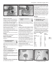
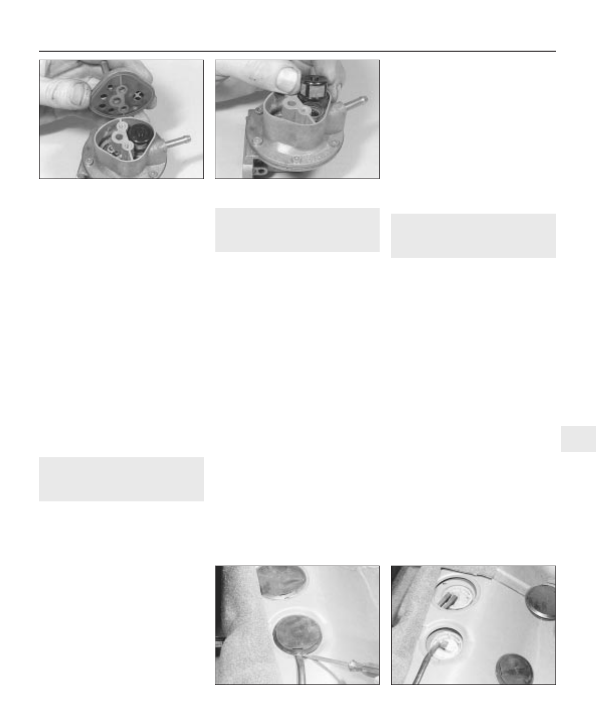
16 Fit the filter screen and cover with gasket.
Refitting
17 Refitting to the cylinder head is a reversal
of removal, but fit a new gasket.
Electric fuel pump
18 Refer to the procedures contained in Part
B, Section 5.
6 Fuel gauge sender unit -
removal and refitting
3
Note: Observe the precautions in Section 1
before working on any component in the fuel
system.
Removal
1 Disconnect the battery negative lead.
2 Raise the rear seat cushion.
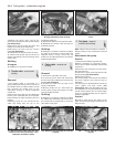
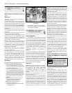
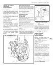
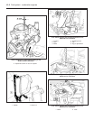
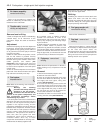
3 Remove the circular plastic cover to expose
the sender unit (see illustrations).
4 Disconnect the electrical lead.
5 Using a suitable tool, unscrew the sender
unit mounting plate to release it from the
securing tabs.
6 Withdraw the sender unit, taking care not to
damage the float as it passes through the hole
in the tank.
Refitting
7 Refitting is a reversal of removal, but use a
new sealing ring if there is any doubt about
the condition of the original one.
7 Fuel tank - removal and
refitting
3
Note: Observe the precautions in Section 1
before working on any component in the fuel
system.
Removal
1 Before the tank can be removed, it must be
drained of as much fuel as possible. To avoid
the dangers and complications of fuel
handling and storage, it is advisable to carry
out this operation with the tank almost empty.
Any fuel remaining can be drained as follows.
2 Disconnect the battery negative lead.
3 Using a hand pump or syphon inserted
through the filler neck, remove any remaining
fuel from the bottom of the tank.
4 Chock the front wheels then jack up the
rear of the car and support it on axle stands
(see “Jacking and vehicle support”).
5 Either remove the complete exhaust system
or, on later models, release the support band
on the silencer, and lower the system using a
jack under the tailpipe.
6 Release the handbrake cables from their
fuel tank and other guide sleeves - there is no
need to disconnect the cables.
7 Unbolt and remove the heat shield.
8 Disconnect the wiring from the fuel gauge
sender unit.
9 Unscrew the mounting and safety strap
bolts and nuts, then lower the tank - at the
same time disconnecting the filler, breather
and supply hoses.
10 If the tank is contaminated with sediment
or water, remove the fuel gauge sender unit as
described previously and swill the tank out
with clean fuel. The tank is moulded from a
synthetic material and if damaged, it should
be renewed. However, in certain cases it may
be possible to have small leaks or minor
damage repaired. Seek the advice of a dealer
or suitable specialist concerning tank repair.
Refitting
11 Refitting is a reversal of removal.
8 Unleaded petrol - general
information and usage
Note: The information given in this Chapter is
correct at the time of writing. If updated
information is thought to be required, check
with a Peugeot dealer. If travelling abroad,
consult one of the motoring organisations (or a
similar authority) for advice on the fuel
available.
The fuel recommended by Peugeot is given
in the Specifications Section of this Chapter.
Only the following models may be operated
on unleaded fuel, and where applicable, the
ignition timing must be retarded as shown
with reference to Chapter 5B:
Engine Code Retard
ignition by
XY7 from
engine No 598051 150D 3°
TU9 C1A None
TU9/K C1A None
TU9A C1A None
TU1 H1A None
TU1/K H1A None
TU3 K1A 4°
TU3A K1G 4°
TU3A/K K1G 4°
TU3S K2A 4°
TU3S/K K2A None
TU3.2/K K2D None
XU51C/K B1F None
Fuel system - carburettor engines 4A•5
4A
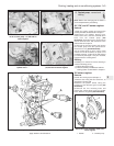
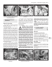
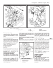
5.7a Removing the fuel pump cover . . . 5.7b . . . and filter
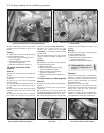
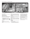
6.3a Remove the circular plastic
covers . . .
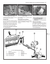
6.3b . . . for access to the sender unit and
fuel supply and return pipes


