sprocket, or fabricate a suitable alternative. If it
will not be necessary to rotate the crankshaft,
the home-made tool described in the text will
suffice.
Removal
1 Disconnect and remove the battery, as
described in Chapter 5A.
2 Remove the air cleaner, complete with
mounting brackets, hot air hose and inlet
hose, with reference to Chapter 4A. Also
remove the inlet cowl.
3 Drain the cooling system, as described in
Chapter 1.
4 Remove the engine oil filler/crankcase
ventilation cap and disconnect the hoses from
the inlet cowl and carburettor.
5 Chock the rear wheels then jack up the
front of the car and support it on axle stands
(see “Jacking and vehicle support”).
6 Disconnect the gearchange selector and
engagement rods with reference to Chapter 7A.
Unscrew the engagement rod nut. Make sure
that the gears are in neutral.
7 Unscrew the bolt and nuts, and disconnect
the exhaust downpipe from the exhaust
manifold.
8 Loosen the left-hand engine mounting nuts
beneath the battery tray so that the mounting
is lowered by approximately 4.0 mm.
9 Disconnect the heater hoses from the
bulkhead, water pump and cylinder head
outlet.
10 Remove the fuel pump, as described in
Chapter 4A.
11 Disconnect the top hose from the
thermostat housing.
12 Disconnect the temperature sender
wiring.
13 Remove the distributor, as described in
Chapter 5B.
14 Disconnect the spark plug HT leads and
remove them from the rocker cover.
15 Disconnect the throttle and choke cables,
as described in Chapter 4A.
16 Disconnect the brake servo vacuum hose
from the inlet manifold (if applicable) and
place to one side.
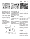
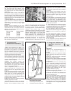
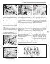
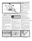
17 Unscrew and remove the two bolts
securing the right-hand rear engine mounting
to the subframe (see illustration).
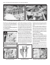
18 Using a suitable long bar inserted through
the right-hand rear engine mounting bracket,
lever up the rear of the engine as far as
possible, without damaging the radiator, and
support with a block of wood (see
illustration). If necessary, loosen the left-hand
engine mounting to gain extra height. Make
sure that the right-hand front mounting is not
damaged by excessive twisting.
19 Unbolt the rocker cover and remove the
gasket.
20 Turn the engine on the crankshaft pulley
nut until the key slot in the camshaft is facing
upwards, then remove the ignition timing
aperture cover and turn the engine as
necessary until the mark on the flywheel is
aligned with the TDC mark on the timing
plate (refer to Chapter 5B if necessary).
Pistons No 2 and 3 will be at TDC.
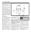
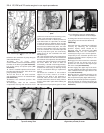
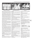
21 Extract the fuel pump plunger from the
timing cover (see illustration).
22 Unbolt the access plate from the top of
the timing cover.
23 Unscrew and remove the camshaft
sprocket retaining bolt from the end of the
camshaft using an Allen key (retain the
sprocket with a suitable bar) (see
illustration).
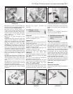
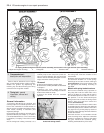
24 Loosen the four bolts securing the timing
cover to the cylinder head (see illustration).
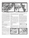
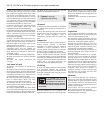
25 Progressively unscrew the cylinder head
bolts in the order shown (see illustration),
and recover the nuts from their channels in
the crankcase.
XV, XW and XY series engine in-car repair procedures 2A•7
2A
7.17 Right-hand rear engine mounting
bolts
7.18 Lever up the engine and support it on
a wooden block
7.21 Removing the fuel pump plunger
7.23 Unscrew and remove the camshaft
sprocket bolt
7.24 Loosen the bolts securing the timing
cover to the cylinder head
7.25 Sequence for tightening or loosening the cylinder head bolts


