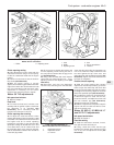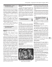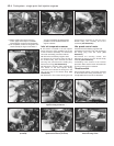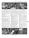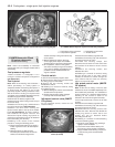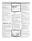
Inlet air temperature sensor
22 The sensor is screwed into the top of the
inlet manifold.
23 Disconnect the battery negative lead.
24 Release the securing clip, and disconnect
the wiring plug from the sensor.
25 Unscrew the sensor and withdraw it.
26 Refitting is a reversal of removal.
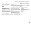
Throttle body
Note: Refer to the warning note in Section 1
before proceeding.
27 Disconnect the battery negative lead.
28 Remove the air inlet trunking from the top
of the throttle body.
29 Disconnect the throttle cable (see Sec-
tion 3).
30 Release the securing clips, then
disconnect the wiring plugs from the fuel
injector (remove the rubber throttle
body/trunking seals to release the wiring),
throttle switch, and the idle speed control
motor (MMFD G6 system only).
31 Disconnect the fuel hoses from the unions
on the throttle body, labelling the hoses to
ensure correct refitting. Plug the open ends of
the hoses, to prevent dirt ingress and further
loss of fuel.
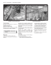
32 Disconnect the vacuum pipes and hoses
from the throttle body unions. Label the hoses
so that they can be correctly reconnected.
33 Unscrew the studs securing the throttle
body to the inlet manifold, and withdraw the
assembly. Recover and discard the gasket.
34 If desired, the two halves of the throttle
body (upper and lower) can be separated by
removing the securing screws. Note that in
this case, a new gasket must be used on
reassembly.
35 Refitting is a reversal of removal, bearing
in mind the following points.
a) Renew all disturbed gaskets and seals,
and use suitable thread locking
compound where necessary.
b) Check the throttle cable operation and
adjustment (Section 3).
c) Ensure that all vacuum hoses and pipes
are correctly reconnected as noted before
removal.
d) When reconnecting the manifold absolute
pressure sensor hose, ensure that it is
routed so that it falls steadily from the
sensor to the throttle body. This is
necessary to prevent any fuel droplets
from entering the sensor (no fuel vapour
trap is fitted), allowing them to drain into
the throttle body instead.
e) Ensure that the fuel hoses are correctly
reconnected, as noted before removal.
f) On completion, switch on the ignition,
and check carefully for signs of fuel
leakage from all disturbed unions. If any
signs of leakage are detected the problem
must be rectified before the engine is
started.
Manifold absolute pressure
sensor
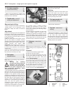
36 Disconnect the battery negative lead.
37 Release the securing clip, and disconnect
the wiring plug from the idle speed control
motor (MMFD G6 systems only).
38 Slacken the clamp (if fitted), and
disconnect the vacuum hose from the sensor.
39 Remove the securing screws and
withdraw the sensor, complete with bracket,
from the body front panel (or wing panel, as
applicable).
40 Refitting is a reversal of removal, but note
the following. When reconnecting the vacuum
hose to the sensor ensure that the hose is
routed so that it falls steadily from the sensor
to the throttle body. This is necessary to
prevent any fuel droplets from entering the
sensor (no fuel vapour trap is fitted), allowing
them to drain into the throttle body instead.
Coolant temperature sensor
Refer to Chapter 3, Section 7.
Electronic control unit (ECU)
Refer to Section 11, paragraphs 29 to 34.
Fuel injection system fuses and
relays
Refer to Section 11, paragraphs 35 to 37.
13 Inlet manifold - removal and
refitting
3
The procedure is essentially as described in
Part A, Section 11, but remove the throttle
body as described in Section 11 or 12 of this
Part and ignore any references to carburettor.
Fuel system - single-point fuel injection engines 4B•7
4B


