8 Rear brake caliper (1.9 GTI
models) - removal, overhaul
and refitting
3
Note: Before starting work, refer to the
warning at the beginning of Section 2
concerning the dangers of hydraulic fluid, and
to the warning at the beginning of Section 6
concerning the dangers of asbestos dust.
Removal
1 Remove the brake pads as described in
Section 6.
2 To minimise fluid loss, unscrew the master
cylinder reservoir filler cap and place a piece
of polythene over the filler neck. Secure the
polythene with an elastic band ensuring that
an airtight seal is obtained. Alternatively, use a
brake hose clamp, a G-clamp, or a similar tool
with protected jaws, to clamp the rear flexible
hydraulic hose.
3 Clean the area around the hydraulic hose-
to-caliper union, then slacken the hose union
half a turn. Be prepared for fluid spillage.
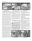
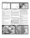
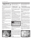
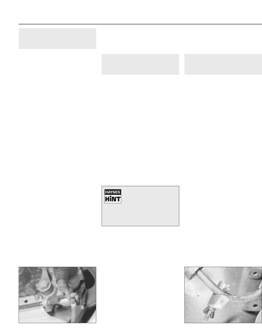
4 Unhook the handbrake cable from the lever
on the caliper, and withdraw the outer cable
(see illustration).
5 Unscrew the two mounting bolts, withdraw
the caliper from the disc, then unscrew the
caliper from the brake hose. Plug the hose to
prevent loss of fluid.
Overhaul
6 This is essentially the same procedure as
that described in Section 7 for the front
caliper.
Refitting
7 To refit the caliper, first screw it onto the
brake hose and locate it over the brake disc,
so that the hose is not twisted.
8 Clean the mounting bolt threads, and apply
a little locking fluid. Insert the bolts together
with the anti-rotation plate, and tighten them
to the specified torque.
9 Tighten the brake hose union.
10 Insert the handbrake outer cable, and
re-connect the inner cable to the lever.
11 Refit the brake pads as described in
Section 6.
12 Remove the brake hose clamp or
polythene sheeting, and bleed the hydraulic
system as described in Section 2.
13 Check and if necessary adjust the
handbrake, as described in Section 15.
9 Brake disc - inspection,
removal and refitting
2
Note: Before starting work, refer to the
warning at the beginning of Section 4
concerning the dangers of asbestos dust.
Inspection
Note: If a disc requires renewal, BOTH discs
on the same axle should be renewed at the
same time (ie both front or both rear) to ensure
even and consistent braking. New brake pads
should also be fitted.
1 Remove the brake pads as described in
Section 4 or 6 as applicable.
2 Inspect the disc friction surfaces for cracks
or deep scoring (light grooving is normal and
may be ignored). A cracked disc must be
renewed; a scored disc can be reclaimed by
machining provided that the thickness is not
reduced below the specified minimum.
3 Check the disc run-out using a dial test
indicator with its probe positioned near the
outer edge of the disc. If the run-out exceeds
the figures given in the Specifications,
machining may be possible, otherwise disc
renewal will be necessary.
4 Excessive disc thickness variation can also
cause judder. Check this using a micrometer.
No actual thickness variation figures are
provided by the manufacturer, but as a
general guide, 0.010 mm should be
considered a maximum.
Removal
5 On certain models, it may be necessary to
remove the brake caliper with reference to
Section 7 or 8 in order to allow sufficient
clearance to remove the disc. Note that there
is no need to disconnect the flexible hose
from the caliper. Support the caliper with wire
or string, taking care not to strain the hose.
6 To remove the disc, unscrew the two
cross-head screws (where fitted) and
withdraw the disc, tilting it as necessary to
clear the hub and caliper if the caliper is still
fitted.
Refitting
7 Refitting is a reversal of removal, but make
sure that the disc-to-hub mating surfaces are
clean and that the securing screws are tight-
ened fully. If the caliper has been removed,
coat the caliper mounting bolt threads with
locking fluid on refitting. Refer to Section 4 or
6 when refitting the disc pads.
10 Rear wheel cylinder -
removal, overhaul and refitting
2
Note: Before starting work, refer to the
warning at the beginning of Section 2
concerning the dangers of hydraulic fluid, and
to the warning at the beginning of Section 5
concerning the dangers of asbestos dust.
Removal
1 Chock the front wheels then jack up the
rear of the car and support it on axle stands
(see “Jacking and vehicle support”). Remove
the rear roadwheels and ensure that the
handbrake is released.
2 Remove the hub/drum, as described in
Section 11.
3 Note the location of the brake shoe upper
return spring then unhook and remove it.
4 Pull the handbrake lever on the rear shoe
fully forwards so that the upper ends of the
shoes are clear of the wheel cylinder. Wedge
the lever in this position using a block of
wood.
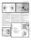
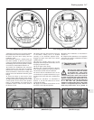
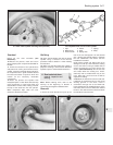
5 To minimise fluid loss, unscrew the master
cylinder reservoir filler cap and place a piece
of polythene over the filler neck. Secure the
polythene with an elastic band ensuring that
an airtight seal is obtained. Alternatively, use a
brake hose clamp, a G-clamp, or a similar tool
with protected jaws, to clamp the flexible
hydraulic hose supplying the rear brakes (see
illustration).
6 Unscrew the hydraulic pipe union nut from
the rear of the wheel cylinder.
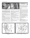
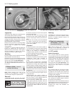
7 Unscrew the two mounting bolts and
withdraw the wheel cylinder from the
backplate (see illustration). Take care not to
spill any brake fluid on the brake shoe linings.
8 Clean the exterior of the wheel cylinder.
Note that on all models with a diagonally split
hydraulic circuit the rear wheel cylinders
incorporate compensators which must not be
dismantled.
9•10 Braking system
8.4 Handbrake cable attachment at rear
brake caliper
10.5 To minimise fluid loss, fit a brake
hose clamp to the flexible hose
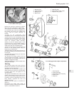
If a dial test indicator is not
available, check the run-out
by positioning a fixed pointer
near the outer edge, in
contact with the disc face. Rotate the
disc and measure the maximum
displacement of the pointer with feeler
blades.


