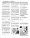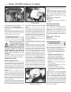
of air cleaner, the end (or top) cover is
retained by a number of spring clips.
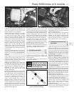
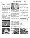
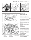
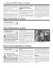
6 Extract the element (see illustration).
7 Discard the element and wipe the casing
interior clean.
8 Insert the new element then refit the end
cover and air duct. Ensure that the cover is
correctly seated, to prevent air leaks, before
fastening with the nuts or the clips.
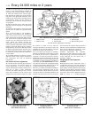
27 Ignition system check
1
Warning: Voltages produced by
an electronic ignition system are
considerably higher than those
produced by conventional
ignition systems. Extreme care must be
taken when working on the system with
the ignition switched on. Persons with
surgically-implanted cardiac pacemaker
devices should keep well clear of the
ignition circuits, components and test
equipment.
1 The ignition system components should be
checked for damage or deterioration as
described under the relevant sub-heading.
Carburettor models
General component check
2 The spark plug (HT) leads should be
checked whenever new spark plugs are fitted.
3 Ensure that the leads are numbered before
removing them, to avoid confusion when
refitting (see Section 27). Pull the leads from
the plugs by gripping the end fitting, not the
lead, otherwise the lead connection may be
fractured.
4 Check inside the end fitting for signs of
corrosion, which will look like a white crusty
powder. Push the end fitting back onto the
spark plug, ensuring that it is a tight fit on the
plug. If not, remove the lead again and use
pliers to carefully crimp the metal connector
inside the end fitting until it fits securely on the
end of the spark plug.
5 Using a clean rag, wipe the entire length of
the lead to remove any built-up dirt and
grease. Once the lead is clean, check for
burns, cracks and other damage. Do not bend
the lead excessively, nor pull the lead
lengthways - the conductor inside might
break.
6 Disconnect the other end of the lead from
the distributor cap. Again, pull only on the end
fitting. Check for corrosion and a tight fit in the
same manner as the spark plug end. If an
ohmmeter is available, check the resistance of
the lead by connecting the meter between the
spark plug end of the lead and the segment
inside the distributor cap. Refit the lead
securely on completion.
7 Check the remaining leads one at a time, in
the same way.
8 If new spark plug (HT) leads are required,
purchase a set for your specific car and
engine.
9 Release the clips or unscrew its retaining
screws and remove the distributor cap. Wipe
it clean, and carefully inspect it inside and out
for signs of cracks, black carbon tracks
(tracking) and worn, burned or loose contacts;
check that the cap’s carbon brush is unworn,
free to move against spring pressure, and
making good contact with the rotor arm. Also
inspect the cap seal for signs of wear or
damage, and renew if necessary. Remove the
rotor arm from the distributor shaft and
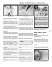
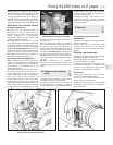
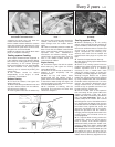
inspect the rotor arm (see illustration). It is
common practice to renew the cap and rotor
arm whenever new spark plug (HT) leads are
fitted. When fitting a new cap, remove the
leads from the old cap one at a time, and fit
them to the new cap in the exact same
location - do not simultaneously remove all
the leads from the old cap, or firing order
confusion may occur. When refitting, ensure
that the arm is securely pressed onto the
shaft, and tighten the cap retaining screws
securely.
10 Even with the ignition system in first-class
condition, some engines may still occasionally
experience poor starting attributable to damp
ignition components. To disperse moisture, a
water-dispersant aerosol can be very
effective.
Ignition timing - check and
adjustment
11 Check the ignition timing as described in
Chapter 5B.
Fuel-injected models
General component check
12 On single-point fuel injection models,
carry out the checks described above in
paragraphs 3 to 8 noting that on some
models the HT leads are removed from the
ignition module, not the distributor cap. On
multi-point fuel injection models, carry out
the checks described above in paragraphs 3
to 10.
Ignition timing - check and
adjustment
13 Refer to Chapter 5B.
28 Idle speed and mixture
check and adjustment
3
1 Before checking the idle speed and mixture
setting, always check the following first:
a) Check the ignition timing (Chapter 5B).
b) Check that the spark plugs are in good
condition and correctly gapped (Sec-
tion 7).
c) Check that the throttle cable and, on
carburettor models, the choke cable
(where fitted) is correctly adjusted
(Section 8 and Chapter 4A, 4B or 4C).
d) Check that the crankcase breather hoses
are secure, with no leaks or kinks (Sec-
tion 29).
e) Check that the air cleaner filter element is
clean (Section 26).
f) Check that the exhaust system is in good
condition (Chapter 4D).
g) If the engine is running very roughly,
check the compression pressures and
valve clearances as described in Chapter
2A, 2B or 2C.
2 Take the car on a journey of sufficient
length to warm it up to normal operating
temperature. Proceed as described under the
relevant sub-heading. Note: Adjustment
should be completed within two minutes of
return, without stopping the engine. If this
cannot be achieved, or if the radiator electric
cooling fan operates, first wait for the cooling
fan to stop. Clear any excess fuel from the
inlet manifold by racing the engine two or
three times to between 2000 and 3000 rpm,
then allow it to idle again.
1•16 Every 24 000 miles or 2 years
26.5c . . . then lift off the top, or end cover 26.6 With the cover removed, withdraw
the filter element
27.9 Remove the rotor arm from the
distributor for inspection


