


SMART-MR10/15 User Manual Rev 5 83
A.4 Connector Cables
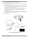
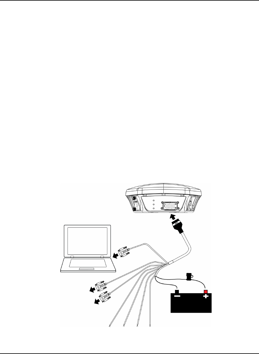
A.4.1 Evaluation Cable (Part Number 01018515)
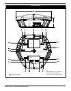
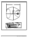
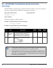
The SMART-MR10/15 evaluation cable provided with Development Kit, is illustrated in Figure 36
and equipped as follows:
• Exposed power wires (red for positive and black for negative) are connected to a 12 or 24V
vehicular power circuit (or equivalent), which must be protected by a user-supplied 5A fuse
(NovAtel recommends an automotive blade-type fuse rated for 5A with an operating voltage of
more than 36 V).
• Three DB-9 connectors. One of these is normally connected to a PC/laptop serial (RS-232)
communication port and another to a modem or radio transmitter, to propagate differential
corrections (refer to your user-supplied modem or radio transmitter user guide for more
information).
• Four pairs of bare wires, where the outer insulation is cut away but the wires beneath are intact.
These are provided for emulated radar, MKI, PPS, and CAN bus. See Table 11 on page 84 for
their pinouts and use. For more information on mating connectors and part numbers, see Table 13
on page 87.
• Some COM port pin-out differences exist between the SMART-MR10 and the SMART-MR15.
Note cable labels.
This cable is RoHS compliant.
Figure 36: SMART-MR10/15 Evaluation Cable
COM1
ER PPS MKI CAN
User supplied
5A fast blow fuse
Tyco 23-pin
connector
SMART-MR10: COM2
SMART-MR15: AUX
SMART-MR10: AUX
SMART-MR15: Not used