26 SMART-MR10/15 User Manual Rev 5
Chapter 2 Installation
This chapter contains instructions for mounting and cabling your SMART-MR10/15.
2.1 Additional Equipment Required
The following additional equipment is required:
• Mounting kit (see Section 2.1.1, Mounting Kits for details of mounting kits
available for the SMART-MR10/15)
• SMART-MR10/15 cable (see Appendix D Replacement Parts starting on page 126
for part numbers). Refer to Figure 8, SMART-MR10 Streamlined Cabling on page
32 for COM and power connections.
• A fused power supply (user-supplied)
2.1.1 Mounting Kits
Several NovAtel mounting kits are available, all of which come with four 1/4-20 screws for mounting
the SMART-MR10/15 to the mounting plate:
• Mounting Kit, Quick Release Plate (part number 01018625), shown in Figure 3 on page 27.
• Mounting Kit, Quick Release Assembly (part number 01018578), shown in Figure 4 on page 28.
• Mounting Kit, AG GPS 262 (part number 01018623), shown in Figure 5 on page 29.
• Mounting Kit, 5/8 Inch Adapter (part number 01018624), shown in Figure 6 on page 30.
When you are using your own mounting plate, adhere to the following guidelines for
maximum and minimum mounting-screw length:
The Mounting Kit, Quick Release Assembly (part number 01018578) includes a
Mounting Kit, Quick Release Plate (part number 01018625).
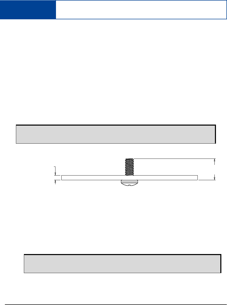
To ensure proper installation of your mounting plate to the SMART-MR10 and
SMART-MR15 units, the total length of the mounting screws must be:
- [T” + 0.45”] maximum and [T” + 0.25”] minimum for 1/4-20 screws or
- [Tmm + 11.5mm] maximum and [Tmm + 7mm] minimum for M6x1 screws.
Total Length
of Screw
Thickness of
Mounting Plate (T)


